A row of 15 decorative lights, connected in series, is connected to a power supply. When the supply is switched on, the lights do not work. The owner uses a voltmeter to test the circuit. When the voltmeter is connected across the third bulb in the row of lights, a reading of zero is obtained.
Which of the following cannot be the only fault in the circuit?
- The filament of the third bulb has broken
- The fuse in the mains transformer has blown
- The filament of one of the other bulbs has broken
- There is a break in the wire from the supply to the transformer
Show/Hide Answer
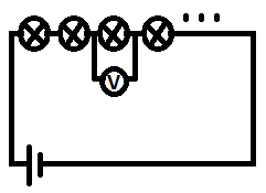
If the filament of the 3rd bulb is broken, it is essentially an open circuit (no current is flowing) Hence, the voltmeter should read the value of the emf, and should not be zero.
Answer: 1
The terminal voltage of a battery is observed to change when the battery supplies a current to an external resistor.
What quantities are needed to calculate the change in voltage?
- the battery’s e.m.f. and its internal resistance
- the battery’s e.m.f. and the current
- the current and the external resistance
- the current and the internal resistance of the battery
Show/Hide Answer
When no current passes through the external resistor, the terminal voltage of a battery is given by the e.m.f. of the battery.
When a current passes through the external resistor, the terminal voltage of a battery is given by the potential difference across the external resistor = IR = $\epsilon – Ir$.
From the above equation, we can see that the change in voltage is $- Ir$.
Answer: 4
3 is not the answer as you will need the $\epsilon$ in addition to the current and external resistance to calculate the change in voltage.