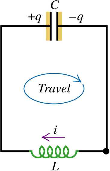
We shall look at an important circuit – one containing an inductor and a capacitor.
From Kirchhoff’s loop rule,
$$\begin{aligned} -L\frac{di}{dt} &=\frac{q}{C} \\ L\frac{di}{dt} + \frac{q}{C} &= 0 \\ \frac{d^{2}q}{dt^{2}} + \frac{1}{LC}q &= 0 \end{aligned}$$
Solving the differential equation above, will give:
$$\begin{aligned} q &= Q \cos{\left( \omega t + \phi \right)} \\ i &=-\omega Q \sin{\left( \omega t + \phi \right)} \end{aligned}$$
where the angular frequency, $\omega = \sqrt{\frac{1}{LC}}$.
The constants Q and $\phi$ are determined by the initial conditions.
Recall that the electric field energy in the capacitor is given by $\frac{q^{2}}{2C}$, which is:
$$\frac{q^{2}}{2C} = \frac{Q^{2}}{2C} \cos^{2}{\left( \omega t + \phi \right)}$$
The L-C circuit is a conservative system – the total energy in the L-C circuit is constant. Let’s calculate the energy stored in the inductor at any time:
$$\begin{aligned} \frac{Q^{2}}{2C}-\frac{q^{2}}{2C} &= \frac{Q^{2}}{2C} \left[ 1-\cos^{2}{\left( \omega t + \phi \right)} \right] \\ &= \frac{Q^{2}}{2C} \sin^{2}{\left( \omega t + \phi \right)} \\ &= \frac{1}{2} L \omega^{2} Q^{2} \sin^{2}{\left( \omega t + \phi \right)} \\ &= \frac{1}{2} L i^{2} \end{aligned}$$
This is the magnetic-field energy in the inductor at any time. The total energy oscillates between the electric and magnetic forms.
Step-by-step process in a L-C circuit
- Capacitor has maximum charge so no current flows.
- Capacitor discharges, current flows counter-clockwise and increases.
- The capacitor has zero charge. Current is at its maximum value and flows counter-clockwise
- Capacitor charges with opposite polarity. Current flow counter-clockwise and decreases.
- Capacitor has maximum charge so no current flows.
- Capacitor discharges, current flows clockwise and increases.
- Capacitor has zero charge. Current is at maximum value and flows clockwise.
- Capacitor charges with original polarity. Current flows clockwise and decreases.
In an oscillating L-C circuit, energy is transferred between magnetic energy in the inductor $\left( U_{B} \right)$ and electric energy in the capacitor $\left( U_{E} \right)$ – electrical oscillation.
The oscillating L-C circuit is very similar to a mass-spring system which undergoes simple harmonic motion. In the table below, we shall compare the oscillation of a mass-spring system with electrical oscillation in an L-C circuit.
| Mass-Spring System | Inductor-Capacitor Circuit |
|---|---|
| Kinetic energy = $\frac{1}{2} mv^{2}_{x}$ | Magnetic energy = $\frac{1}{2} L i^{2}$ |
| Potential energy = $\frac{1}{2} k x^{2}$ | Electric energy = $\frac{q^{2}}{2C}$ |
| $\frac{1}{2} mv_{x}^{2} + \frac{1}{2} kx^{2} = \frac{1}{2} kA^{2}$ | $\frac{1}{2} Li^{2} + \frac{q^{2}}{2C} = \frac{Q^{2}}{2C}$ |
| $v_{x} = \pm \sqrt{\frac{k}{m}} \sqrt{A^{2} – x^{2}}$ | $i = \pm \sqrt{\frac{1}{LC}}\sqrt{Q^{2}-q^{2}} $ |
| $v_{x} = \frac{dx}{dt}$ | $i = \frac{dq}{dt}$ |
| $\omega = \sqrt{\frac{k}{m}}$ | $\omega = \sqrt{\frac{1}{LC}}$ |
| $x = A \cos{\left(\omega t + \phi \right)}$ | $q = Q \cos{\left(\omega t + \phi \right)}$ |
Next: Magnetic-Field Energy In Inductor