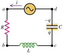
Consider a series circuit containing a resistor R, an inductor L, and a capacitor C, through which there is a sinusoidal current, $i = I \cos{\omega t}$. We will consider the steady-state condition.
We will look at the voltage across resistor:
$$\begin{aligned} v_{R} &= iR \\ &= IR \cos{\omega t} \\ &= V_{R} \cos{\omega t} \end{aligned}$$
Voltage across inductor:
$$\begin{aligned} v_{L} &= IX_{L} \cos{\left( \omega t + 90^{\circ} \right)} \\ &= V_{L} \cos{\left( \omega t + 90^{\circ} \right)} \\ &=-V_{L} \sin{\omega t} \end{aligned}$$
Voltage across capacitor:
$$\begin{aligned} v_{C} &= IX_{C} \cos{\left( \omega t-90^{\circ} \right)} \\ &= V_{C} \cos{\left( \omega t-90^{\circ} \right)} \\ &= V_{C} \sin{\omega t} \end{aligned}$$
The source voltage:
$$\begin{aligned} v &= v_{R} + v_{L} + v_{C} \\ &= V_{R} \cos{\omega t}-\left( V_{L}-V_{C} \right) \sin{\omega t} \\ &= V \left[ \frac{V_{R}}{V} \cos{\omega t}-\frac{V_{L}-V_{C}}{V} \sin{\omega t} \right] \\ &= V \cos{\left( \omega t + \phi \right) }\end{aligned}$$
Note that we have used the R-formula to simplify the trigonometric functions, the constants are as follows:
$$\begin{aligned} V &= \sqrt{V_{R}^{2} + \left( V_{L}-V_{C}\right)^{2}} \\ \cos{\phi} &= \frac{V_{R}}{V} \\ \sin{\phi} &= \frac{V_{L}-V_{C}}{V} \end{aligned}$$
The impedance of an A.C. circuit is the ratio of the voltage amplitude across the circuit to the current amplitude in the circuit. The impedance of the L-R-C circuit is:
$$\begin{aligned} Z &= \frac{V}{I} \\ &= \frac{\sqrt{V_{R}^{2} + \left( V_{L}-V_{C}\right)^{2}}}{I} \\ &= \frac{\sqrt{I^{2}R^{2} + \left( IX_{L}-IX_{C} \right)^{2}}}{I} \\ &= \sqrt{R^{2} + \left( X_{L}-X_{C} \right)^{2}} \\ &= \sqrt{R^{2} + \left( \omega L-\frac{1}{\omega C} \right)^{2}} \end{aligned}$$
$$\begin{aligned} \tan{\phi} &= \frac{\sin{\phi}}{\cos{\phi}} \\ &= \frac{V_{L}-V_{C}}{V_{R}} \\ &= \frac{X_{L}-X_{C}}{R} \\ &= \frac{\omega L-\frac{1}{\omega C}}{R} \end{aligned}$$
Since the circuit elements are connected in series, the current i at any instant in the same at every point in the circuit, and a single phasor $I$ represents the current in all circuit elements.
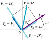
The angle $\phi$ between phasors V and I is the angle by which the source voltage v leads the current i.
The phasor V representing the total voltage is the vector sum of the phasors for the individual voltages: $V_{R}$, $V_{L}$ and $V_{C}$
Next: Resonance & Power In A.C. Circuits
Previous: Resistors, Inductors & Capacitors In A.C. Circuits