Series, parallel and potential-divider networks
Key idea: Circuit networks are solved by combining two conservation ideas: charge flow at junctions and energy transfer around loops.
Continue where you stopped
The core idea
H1 Physics 8867 · Lesson 3 of 3
Check your understandingBy the end of this lesson, you should be able to
- Find combined resistance for series and parallel groups.
- Solve mixed networks from one source.
- Analyse unloaded and loaded potential dividers, including NTC thermistors and LDRs.
Learn the idea
Big question: How do charge conservation and energy conservation guide every series, parallel and divider calculation?
Reduce networks without losing the physics
Series components carry the same current and their p.d.s add, so their resistances add. Parallel branches share p.d. and branch currents add, giving the reciprocal rule.
Simplify one recognisable group at a time, redraw if necessary, then work back. A parallel equivalent must be smaller than its smallest branch resistance; this is a useful error check.
Check your understanding: Why is current not necessarily shared equally at a junction?
Parallel branches have the same p.d., but different resistances produce different currents.
Make a sensor divider respond in the intended direction
For an unloaded divider, Vout = VinRout/(Rtop + Rout), where Rout is the resistance directly across which output is measured. Sensor position determines whether output rises or falls.
A load across Rout is in parallel with it. This lowers the effective lower resistance and usually changes the output, so the unloaded formula cannot be used unchanged.
Check your understanding: An LDR is the lower resistor and Vout is across it. What happens to Vout as light increases?
LDR resistance falls, so it takes a smaller fraction of the input and Vout falls.
Fixed and variable potential-divider circuits
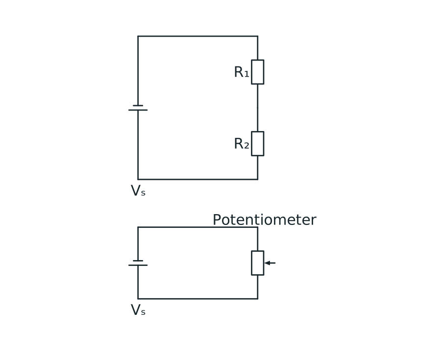
The upper circuit has resistors R1 and R2 in series across a supply, with output voltage measured across the lower resistor R2. The lower circuit has a three-terminal potentiometer across a supply, with output measured from its slider to the zero-volt end.
View figure data
| Circuit | Connection |
|---|---|
| Fixed divider | R₁ and R₂ are in series; output is across R₂ |
| Variable divider | The potentiometer track is across the supply; output is taken from its wiper |
Key ideas
- Same current in series; same p.d. in parallel.
- Equivalent resistance is not found by averaging branch values.
- Define exactly which resistor the output is measured across.
Relationships to know
Rseries = R₁ + R₂ + …1/Rparallel = 1/R₁ + 1/R₂ + …Vout = Vin Rout/(Rtop + Rout) for an unloaded divider
Follow the reasoning
Worked example
Analyse a loaded potential divider
Question: A 12 V divider has 3.0 kΩ on top and 6.0 kΩ below. A 6.0 kΩ load is connected across the lower resistor. Find unloaded and loaded output p.d.s.
Step 1: Find unloaded output
Why: Before loading, the lower resistor alone determines the output fraction.
Working: Vout = 12[6.0/(3.0 + 6.0)] = 8.0 V.
Step 2: Replace the loaded section
Why: The load and lower resistor share both nodes and are parallel.
Working: Rlower,eff = 6.0 || 6.0 = 3.0 kΩ.
Step 3: Apply the divider again
Why: The source now sees equal upper and effective lower resistances.
Working: Vout,loaded = 12[3.0/(3.0 + 3.0)] = 6.0 V.
Answer: Unloaded output is 8.0 V; the load reduces it to 6.0 V.
Check: Adding a parallel load lowers the lower resistance, so a smaller output fraction is expected.
Now try it with support
Practise with support
A 4.0 Ω resistor is in series with a parallel pair of 6.0 Ω and 3.0 Ω. Find the total resistance.
Hints
- Combine the parallel pair first.
- Then add the series resistance.
View the guided answer
Rparallel = (6.0 × 3.0)/(6.0 + 3.0) = 2.0 Ω. Rtotal = 4.0 + 2.0 = 6.0 Ω.
Your turn
Practise independently
A 4.0 kΩ–6.0 kΩ potential divider is connected to 10 V, then a 6.0 kΩ load is placed across the lower resistor. Calculate the loaded output voltage.
Check your answer
The 6.0 kΩ lower resistor in parallel with the 6.0 kΩ load has equivalent resistance 3.0 kΩ. The loaded divider is therefore 4.0 kΩ above 3.0 kΩ, so Vout = 10[3.0/(4.0 + 3.0)] = 4.29 V.
Common mistakes and exam guidance
Watch out for
- Dividing p.d. equally between unequal series resistors.
- Using the unloaded divider formula after attaching a finite load.
In an exam
- Redraw a loaded divider to show the parallel pair before calculating.
- Check limiting behaviour: as an NTC thermistor warms its resistance falls; decide how that changes the measured fraction.
Put the ideas together
Exam-style practice [8 marks]
A 9.0 V temperature alarm uses a 4.0 kΩ fixed resistor above an NTC thermistor, with Vout measured across the thermistor. Its resistance falls from 8.0 kΩ to 2.0 kΩ when hot. Find both outputs. The alarm needs a rising voltage when hot: redesign the divider and explain your choice. Then find the hot output if a 4.0 kΩ alarm input loads the output.
Plan before you answer
- Calculate the stated divider first.
- Swap sensor position for the opposite response.
- For loading, replace the output section by a parallel equivalent.
View the marking points and model answer
Marking points
- Cold output = 6.0 V.
- Hot output = 3.0 V.
- Places NTC on top and fixed resistor below for rising hot output.
- Explains warming lowers top resistance/increases lower voltage fraction.
- Finds hot unloaded redesigned output = 6.0 V.
- Finds lower loaded resistance 4.0 || 4.0 = 2.0 kΩ.
- Finds loaded hot output = 4.5 V.
- Recognises loading reduces the expected output.
Model answer
Initially Vcold = 9[8/(4+8)] = 6.0 V and Vhot = 9[2/(4+2)] = 3.0 V, so this arrangement falls with temperature. Put the NTC on top and measure across the 4.0 kΩ fixed resistor below; then warming reduces the top resistance and the output rises to 9[4/(2+4)] = 6.0 V. With a 4.0 kΩ input across the lower 4.0 kΩ resistor, their equivalent is 2.0 kΩ, so the hot loaded output is 9[2/(2+2)] = 4.5 V.
Finish from memory
Three-question recap
What is shared by parallel branches?
Check
Potential difference.
What is shared by series components?
Check
Current.
How is a load across a divider output combined?
Check
In parallel with the output resistor.
Continue with the next resource in this course.
Course and syllabus information
- Course
- GCE A-Level H1 Physics
- Edition
- GCE A-Level H1 Physics 2027