Energy Losses In Transformer
Key idea: Identify the main transformer losses (I²R, eddy currents, hysteresis, flux leakage) and the design features used to reduce them (A Level Physics).
Continue where you stopped
The core idea
On this page
Learning objectives
- Explain energy losses in practical transformers and the design features that reduce them beyond the H2 syllabus.
1. Definitions (Must Know)
A. Efficiency idea
A real transformer is efficient but not perfect: some input power becomes unwanted heating or is lost because not all flux links the secondary.
2. Key Ideas (What Earns Marks)
Main loss mechanisms:
| Loss | What causes it | Typical reduction method |
|---|---|---|
| Copper loss | resistance of windings → I²R heating | low-resistance copper wire, thicker wire |
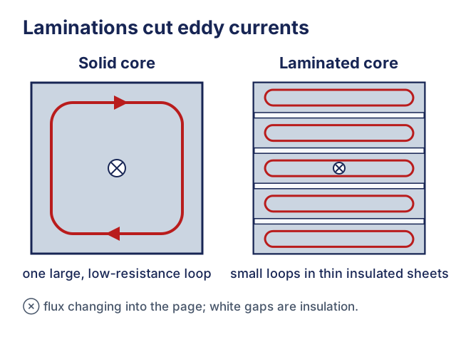
| Eddy current loss | induced currents in the core | laminated core (thin insulated sheets) |
| Hysteresis loss | repeated magnetisation of the core | soft iron / low-hysteresis material |
| Flux leakage | not all primary flux links secondary | good core design, close coupling |
Simple iron-core transformer operation and ideal ratios are core outcome 18g. Detailed loss mechanisms are useful extension material rather than a separately named 9478 requirement.
3. Detailed Explanations
A. Eddy current loss and lamination
Changing flux in the core induces currents in the metal core. Those eddy currents dissipate energy as heat.
Lamination reduces this by breaking up large current loops into small loops with higher resistance.
B. Hysteresis loss (qualitative)
In a.c. operation, the core is repeatedly magnetised and demagnetised. This process uses energy each cycle, which appears as heat. Using soft iron (low hysteresis) reduces this loss.
C. Flux leakage
If some magnetic flux produced by the primary does not link the secondary, less energy is transferred to the load. A well-designed core improves coupling.
4. Common Mistakes
- Saying “lamination reduces hysteresis loss” (it mainly reduces eddy currents).
- Confusing “flux leakage” (field lines missing the secondary) with “resistance loss” (I²R).
5. Exam Tips
- If asked “how to reduce losses”, give a matched pair: loss → design feature.
- In explanations, keep it causal: “changing flux induces eddy currents → heating”.
6. Worked Examples
Modelled example 1
Match the loss to the fix
Problem
Study the worked solution
Reduce eddy currents
Method
Use a core made from thin insulated laminations.Reason
Lamination interrupts large conducting loops and raises the resistance of induced current paths.Working
laminated core ⇒ I_eddy↓Reduce hysteresis
Method
Use soft iron or another low-hysteresis core material.Reason
It requires less energy for each magnetisation reversal.Working
low-hysteresis material ⇒ E_cycle↓Reduce copper loss
Method
Use thick, low-resistance copper windings.Reason
Lower winding resistance reduces I²R heating at a given current.Working
R↓ ⇒ P_copper = I²R↓
Guided practice 2
Copper loss calculation
Problem
Try this before viewing the solution
Hints
Hint 1: square the current
View solution step by step
Identify the loss model
Method
P_copper = I²R.Reason
The winding behaves as a resistor carrying current.Working
P = I²RCalculate the loss
Method
P_copper = 5.0 W.Reason
Substitute the current and winding resistance stated.Working
P_copper = (2.5)²(0.80) = 5.0 W
Common misconception 3
Efficiency from losses
Learner claim
Try this before viewing the solution
View solution step by step
Add the loss pathways
Method
Total loss is 20 W.Reason
Copper and core losses both remove power from the useful output.Working
Pₗₒₛₛ = 12 + 8 = 20 WFind output power
Method
Pₒᵤₜ = 480 W.Reason
Input power divides between useful output and losses.Working
Pₒᵤₜ = 500-20 = 480 WUse the efficiency ratio
Method
η = 96%.Reason
Efficiency compares useful output with total input.Working
η = 480/500 = 0.96 = 96%
Examiner practice 4
Identify the dominant loss from a symptom
Examination question
Try this before viewing the solution
View solution step by step
Identify core losses
1 markMethod
Eddy-current and hysteresis losses dominate the observed no-load heating.Reason
They occur in the magnetic core whenever it experiences alternating flux.Working
P_core = P_eddy + P_hysteresisExplain why they persist
1 markMethod
The primary still produces changing core flux with no secondary load.Reason
The core continues to be magnetised and demagnetised, and eddy currents are still induced.Working
Φ(t) alternates at no loadCompare copper loss
1 markMethod
Copper loss is relatively small because no-load current is small.Reason
Winding heating scales as I²R.Working
I small ⇒ I²R small
Self-mark with the mark scheme
Compare your response with each mark point. Select a point only when your response contains that evidence.
Self-mark the loss category, alternating-flux cause and current comparison.
Challenge 5
Flux leakage effect (qualitative)
Independent transfer
Try this before viewing the solution
Hints
Hint 1: focus on linked flux
View solution step by step
Identify the linkage change
Method
Less of the primary’s changing flux links the secondary winding.Reason
Leaked field lines do not pass through all secondary turns.Working
NₛΦ_linked < NₛΦ_idealInfer the induced e.m.f.
Method
The secondary e.m.f. is reduced.Reason
Its magnitude depends on the rate of change of secondary flux linkage.Working
|Eₛ| = |d(NₛΦ_linked)/dt|State the observable output
Method
Output voltage under load is lower than the ideal prediction.Reason
The induced secondary e.m.f. supplies that output.Working
V_(out,real) < V_(out,ideal)
7. Mind Stretchers
Mind stretcher 1: Why do laminated sheets need insulation?Extension
Explain why the laminated sheets are insulated from each other.
Show Answer
Insulation stops charge carriers from crossing between sheets, which breaks up large current loops and increases the resistance of any induced currents.
That reduces eddy current magnitude and therefore reduces I²R heating.
Mind stretcher 2: Trade-offs in reducing copper lossExtension
Why can’t we always eliminate copper loss by using extremely thick wire for the windings?
Show Answer
Thicker wire reduces resistance but increases size, mass and cost, and may not fit in the available space.
It can also reduce the number of turns you can pack onto the core, affecting design requirements.
Continue with the next resource in this course.
Course and syllabus information
- Course
- A-level H2 Physics topic extensions
- Syllabus scope
- Beyond the syllabus
- Edition
- A-level H2 Physics topic extensions