Power Distribution
Key idea: Use P = VI and Ploss = I²R to explain high-voltage transmission and solve questions on transmission current, power loss and efficiency (A Level Physics).
Continue where you stopped
The core idea
On this page
Learning objectives
- Use magnetic flux and flux-linkage relationships.
- Apply Faraday's and Lenz's laws to induced e.m.f. and direction.
- Explain simple applications of electromagnetic induction, including motional e.m.f. and eddy currents.
- Explain simple iron-core transformer operation and apply ideal transformer ratios.
1. Definitions (Must Know)
A. Transmission loss (cable heating)
Power lost as heat in transmission cables is:
Pₗₒₛₛ = I²R
where R is the total cable resistance and I is the transmission current.
2. Key Ideas (What Earns Marks)
- For a given transmitted power P: P = VI ⇒ I = P/V
- Substitute into cable loss: Pₗₒₛₛ = I²R = (P/V)²R so increasing V reduces loss strongly (loss ∝ 1/V²).
- Transformers make it practical to:
- step up voltage for transmission (reduce current),
- step down voltage for safe use.
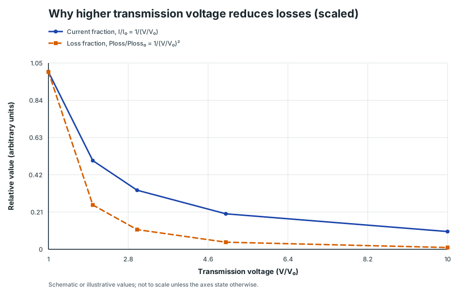
Why higher transmission voltage reduces losses (scaled)
Two curves showing transmission current decreasing as 1/V and cable loss decreasing as 1/V^2 for fixed transmitted power and cable resistance.
Scroll across the graph to read all labels.
View figure data
| Transmission voltage (V/V₀) | Current fraction, I/I₀ = 1/(V/V₀) | Loss fraction, Ploss/Ploss₀ = 1/(V/V₀)² |
|---|---|---|
| 1 | 1 | 1 |
| 2 | 0.5 | 0.25 |
| 3 | 0.333 | 0.111 |
| 5 | 0.2 | 0.04 |
| 10 | 0.1 | 0.01 |
The ideal transformer is core outcome 18g. Grid transmission and I²R loss are valuable applications, but they are treated here as extension context rather than a separately named 9478 outcome.
3. Detailed Explanations
A. Why we don’t just use thick cables
Reducing R needs very thick conductors, which are heavy and expensive.
Reducing I by increasing V is usually the more efficient engineering choice.
B. Why a.c. matters
Transformers need changing flux, so they work with a.c. This is why a.c. is used in large-scale power distribution.
4. Common Mistakes
- Using Pₗₒₛₛ = IV (that is power delivered/absorbed at a potential difference, not specifically cable heating).
- Forgetting that Pₗₒₛₛ depends on I² (current matters a lot).
5. Exam Tips
- If the question keeps power fixed and changes voltage, use the ratio method: Pₗₒₛₛ ∝ 1/V²
- Always state “high voltage → low current → low I²R loss”.
6. Worked Examples
Modelled example 1
Compare losses at two transmission voltages
Problem
Study the worked solution
Find current at 10 kV
Method
I = 100 A.Reason
At fixed transmitted power, current is power divided by transmission voltage.Working
I = (1.0 × 10⁶)/(1.0 × 10⁴) = 100 AFind loss at 10 kV
Method
Pₗₒₛₛ = 2.0 × 10⁴ W.Reason
Cable heating depends on current squared.Working
Pₗₒₛₛ = (100)²(2.0) = 2.0 × 10⁴ WRepeat at 100 kV
Method
I = 10 A and Pₗₒₛₛ = 2.0 × 10² W.Reason
A tenfold voltage increase makes current one tenth and I²R loss one hundredth.Working
I = (1.0 × 10⁶)/(1.0 × 10⁵) = 10 A, Pₗₒₛₛ = 10²(2.0) = 200 W
Guided practice 2
Find the transmission current and loss
Problem
Try this before viewing the solution
Hints
Hint 1: calculate delivered current first
View solution step by step
Calculate transmission current
Method
I = 40 A.Reason
The line carries the stated transmitted power at the stated voltage.Working
I = (2.0 × 10⁶)/(5.0 × 10⁴) = 40 ACalculate cable loss
Method
Pₗₒₛₛ = 2.4 × 10³ W.Reason
Resistive cable heating scales as current squared.Working
Pₗₒₛₛ = 40²(1.5) = 2400 W
Common misconception 3
Required voltage for a maximum allowed loss
Learner claim
Try this before viewing the solution
View solution step by step
Turn the loss limit into a current limit
Method
I ≤ 50 A.Reason
For fixed cable resistance, loss increases with current squared.Working
I ≤ square root of ((1.0 × 10⁴)/4.0) = 50 AFind the boundary voltage
Method
V = 20 kV when the loss is exactly at its maximum.Reason
At the largest permitted current, V = P/I gives the smallest permitted voltage.Working
Vₘᵢₙ = (1.0 × 10⁶)/50 = 2.0 × 10⁴ V = 20 kVInterpret the inequality
Method
The requirement is V ≥ 20 kV, not exactly 20 kV.Reason
Any higher voltage gives lower current and therefore a loss below the cap.Working
Pₗₒₛₛ ≤ 10 kW ⇒ V ≥ 20 kV
Examiner practice 4
Transmission efficiency
Examination question
Try this before viewing the solution
View solution step by step
Find line current
1 markMethod
I = 20 A.Reason
The transmitted power and voltage set the current.Working
I = (5.0 × 10⁵)/(2.5 × 10⁴) = 20 AFind cable loss
2 marksMethod
Pₗₒₛₛ = 1.2 × 10³ W.Reason
Heating is I²R in the total cable resistance.Working
Pₗₒₛₛ = 20²(3.0) = 1200 WFind received power
1 markMethod
P_received = 498,800 W.Reason
Subtract cable heating from the power entering the transmission line.Working
P_received = 500,000-1200 = 498,800 WCalculate efficiency
1 markMethod
η = 99.76%, about 99.8%.Reason
Efficiency is received output divided by transmitted input.Working
η = 498,800/500,000 × 100% = 99.76%
Self-mark with the mark scheme
Compare your response with each mark point. Select a point only when your response contains that evidence.
Self-mark current, I²R loss, received power and efficiency.
Challenge 5
Ratio method
Independent transfer
Try this before viewing the solution
Hints
Hint 1: square the inverse voltage ratio
View solution step by step
Find the voltage factor
Method
Voltage increases by a factor of 4.Reason
60/15 = 4.Working
V₂/V₁ = 4Apply inverse-square scaling
Method
The new loss is 1/16 of the original.Reason
Current falls inversely with voltage, and resistive loss depends on current squared.Working
P_(loss,2)/P_(loss,1) = (15/60)² = 1/16 = 0.0625
7. Mind Stretchers
Mind stretcher 1: Ratio shortcutExtension
If transmission voltage is increased by a factor of 20 (same power, same cable), what happens to Pₗₒₛₛ?
Show Answer
Pₗₒₛₛ ∝ 1/V², so increasing V by 20 reduces loss by 20² = 400.
Mind stretcher 2: Why not “infinite voltage”?Extension
If higher voltage reduces cable losses, why don’t power companies transmit at arbitrarily high voltages?
Show Answer
Very high voltages increase insulation requirements, cost and size of equipment, and risk of electrical breakdown/arcing.
They also raise safety and clearance requirements. In practice there is an optimal engineering/economic trade-off.
Continue with the next resource in this course.
Course and syllabus information
- Course
- GCE A-Level H2 Physics
- Edition
- GCE A-Level H2 Physics 2027