Using a multimeter safely
Key idea: Choose the multimeter's setting, sockets and range for the quantity. Measure current in series, voltage across the component, and resistance only with the supply disconnected and component isolated.
Offline pages
Saved on this device only. Connect at least once every 30 days to confirm Premium. Sign-out or a change of account removes saved copies.
Loading guide controls…
Guided lessons · coming soon
Guided lesson
Guided steps
- Choose connections from the quantity being measured.
- Check the range, unit and lead sockets.
- Convert milliamperes to amperes and trace the series path.
- Record the voltage and choose a range that fits.
- Correct the unsafe current-mode connection.
- Explain the two meter connections for the lamp.
- Plan every change from current mode to resistance mode.
- Record the current in both units and choose the range.
- Explain why other conducting paths change a resistance reading.
On this page
You stopped at:
ContinueA multimeter can measure current, voltage and resistance, but each needs its own setting, and current needs a different connection from the other two. Decide what you are measuring before choosing the setting, the sockets, the range and where the probes go. Use only the low-voltage circuits your teacher provides, never mains electricity.
Settings and connections
- Current: choose a current setting (A or mA) and connect the meter in series, so the current passes through it.
- Voltage: choose a voltage setting (V) and connect the meter across the component, one probe on each side.
- Resistance: switch off and disconnect the power first. Choose a resistance setting (Ω) and put the probes across the component, which must be separated from the rest of the circuit. The meter supplies its own small current.
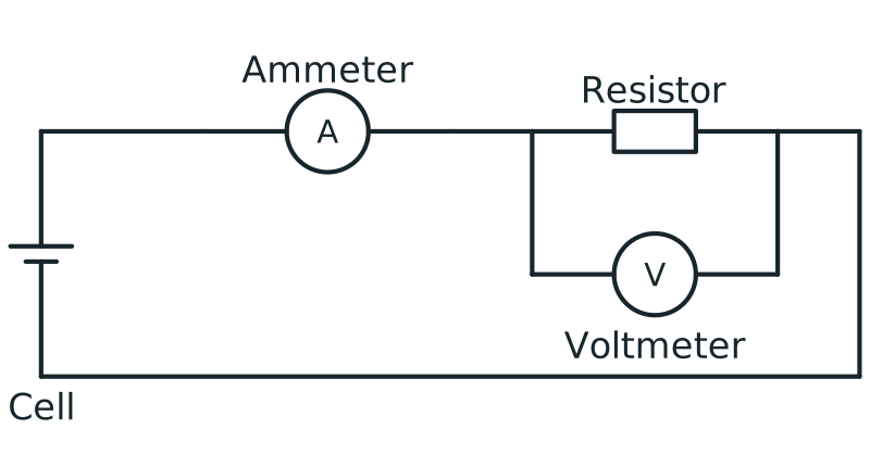
Voltmeter connection in parallel
Circuit with ammeter in series and voltmeter connected in parallel across a resistor to measure potential difference.
Scroll across the figure to read all labels.
View figure data
| Part | Connection |
|---|---|
| Ammeter | In series in the main loop |
| Voltmeter | In parallel across the resistor |
| Resistor | In the conducting loop with the cell and ammeter |
Ranges and units
Each setting has several ranges. The range shows roughly the largest value the meter can display, such as 200 mA or 20 V; some meters choose the range themselves.
- If you do not know what to expect, start on a high range, then switch down if the reading fits a lower one, to see more digits.
- A value too big for the range shows an overload sign, such as “OL” or a single “1”. Switch to a higher range.
- Large currents often need the red lead in a separate socket, such as the 10 A socket.
- Record the unit of the range with the number. On the 200 mA range, a display of 125.4 means 125.4 mA, which is 0.1254 A, because 1 A = 1000 mA.
Ask your teacher to check the circuit before switching on, switch off before changing connections, and never put a meter on a current setting straight across a cell or power supply.
Worked example 1
Read a current measurement with its unit
Problem
A teacher-approved low-voltage circuit has a multimeter in series with a lamp. On the 200 mA range the display reads 125.4. Record the current in mA and A, and explain the connection.
Show full solution
Read the range as well as the display
Method
Use the mA unit given by the selected range.Reason
The number alone is incomplete: 125.4 mA and 125.4 A are very different currents.
Working
Answer
Current = 125.4 mA = 0.1254 A, because 1000 mA = 1 A.
Trace the measurement path
Method
Check that the measured current passes through the meter and lamp in the same branch.
Reason
A current measurement requires the meter in the current path. It must not be placed directly across the supply in current mode.
Working
Answer
Series connection measures the lamp current. The reading fits below the 200 mA range limit.
Quick check
Guided practice 2
Choose a voltage range that can show the reading
Problem
A multimeter on a 20 V range is connected across a lamp and reads 2.84. Record the reading and choose the lowest suitable range from 2 V, 20 V and 200 V.
Record the voltage and choose the range
Hints
Hint 1
Read the dial unit
The selected quantity is voltage, measured in V.
Hint 2
Check the limit
Compare 2.84 V with the largest value on the 2 V range.
Show solution step by step
Identify quantity and connection
Method
Record the value in volts and retain the across-the-lamp connection.
Reason
Voltage mode compares the two terminals of the lamp.
Working
Answer
Potential difference = 2.84 V; the connection is parallel.
Compare the value with the range
Method
Keep a range that can show more than 2.84 V.Reason
A 2 V range cannot display a 2.84 V reading. It will indicate overload rather than a useful extra digit.
Working
Answer
Use the 20 V range. On this example meter the 2 V range shows “OL”; other meters may show a different overload symbol.
Quick check
Spot the mistake 3
Correct an unsafe current measurement
Learner plan
“I will select current mode and place the multimeter probes directly across the cell.” Identify the danger and replace the plan with a safe connection.
Explain the first error and the correction
Show solution step by step
Locate the first unsafe decision
Method
Reject the across-the-cell connection while the meter is in current mode.
Reason
Current mode has very low resistance, so this connection can allow a very large current and damage the meter or source.
Working
Answer
Unsafe: current mode connected directly across the supply.
Rebuild the circuit safely
Method
Switch off, break the intended current path and insert the meter in series.
Reason
The current being measured must pass through the meter without creating a separate low-resistance path.
Working
Answer
Safe: begin on a suitable high range, connect in series, ask for a check, then switch on.
Common mistake
Exam-style question 1
Explain two measurements on one lamp
Problem
Describe how a multimeter is used first to measure a lamp’s current and then its potential difference in a low-voltage circuit. Explain why the two connections differ.
Explain your reasoning before revealing the solution
Show solution step by step
Measure current through the lamp
Method
Switch off, choose current mode and suitable lead sockets, and insert the meter in series.
Reason
The current to be measured must pass through the meter.
Working
Answer
After the teacher checks the connection, switch on and record a current with its unit.
Measure potential difference across the lamp
Method
Switch off before changing leads or connections, choose voltage mode and place one probe on each side of the lamp.
Reason
Potential difference compares two points, so the meter forms a parallel branch across the lamp.
Working
Answer
After checking the setup, switch on and record the potential difference in V. Do not leave the leads in a current-only socket.
Self-mark with the mark scheme
Tick each mark point that your answer includes.
Self-check each part of your method.
Try it yourself 4
Change from measuring current to resistance
Problem
A multimeter is connected in series in a switched-on circuit to measure current. The learner must now measure the resistance of one resistor. Describe every change needed before taking the new reading.
Change the equipment safely
Hints
Hint 1
start with the energy source
Resistance mode must not be used on the still-powered component.
Hint 2
change both setting and connection
Think about the supply, the component, the lead sockets, the mode and where the probes go.
Show solution step by step
Make the component safe to test
Method
Switch off and disconnect the external supply, then isolate the resistor from the circuit.
Reason
The meter supplies its own small test signal in resistance mode, so another live source would make the reading invalid and may damage the meter.
Working
Answer
Power off → supply disconnected → resistor isolated.
Change the meter and connection
Method
Move the leads if the meter requires it, select resistance mode and connect the probes across the resistor.
Reason
Resistance is measured across the isolated component rather than by keeping the current-mode series connection.
Working
Answer
Correct sockets → resistance mode → suitable range → probes across resistor.
Quick check
Check your understanding 1 Choose a current range
On the 200 mA range, a multimeter in series with a lamp shows 45.0. Record the current in mA and in A. In a second circuit the current is expected to be about 0.5 A. Which range should the student use: 20 mA, 200 mA or 10 A?
Show answer
The current is 45.0 mA = 0.0450 A. 0.5 A is 500 mA, which is more than 200 mA, so use the 10 A range, moving the red lead to the 10 A socket if the meter has one.
Check your understanding 2 A wrong resistance reading
A learner disconnects the supply but leaves the resistor connected to other branches. Why might the displayed resistance fail to be the resistor’s own value? What should change?
Show answer
Other conducting paths can carry some of the meter’s test current. Isolate the resistor from those paths, check that external power is removed, and connect the probes across the isolated resistor on resistance mode.
Common mistakes
- Connecting the meter on a current setting across a component or a power supply.
- Measuring resistance while the power is still connected, or while the component is still joined to other paths.
- Reading the display without the unit of the range, such as writing 125.4 A for 125.4 mA.
- Forgetting to move the red lead back after using the 10 A socket.
Spotted an error? Report a correction
Syllabus and review details
- SEC G1 Science 2027 · 2027
Content structure and syllabus content, PDF pages 8–17
Last reviewed: