Half-Wave Rectification
Key idea: Explain half-wave rectification using a single diode and sketch the ideal sinusoidal input and pulsating output waveforms.
Continue where you stopped
The core idea
On this page
Learning objectives
- Analyse mean power in resistive a.c. loads and half-wave rectification.
- Represent sinusoidal a.c. and use peak and r.m.s. values.
1. Definitions (Must Know)
A. Rectification
Rectification converts alternating current (a.c.) into a unidirectional output. Without smoothing, the output is usually pulsating d.c., not a steady value.
B. Diode
A diode is a component that allows current to flow mainly in one direction:
- forward bias: diode conducts (current flows)
- reverse bias: diode blocks (current is approximately zero)
2. Key Ideas (What Earns Marks)
- A single diode in series with a load resistor produces half-wave rectification.
- The output is not steady d.c.; it is pulsating d.c. (zero during half the cycle).
- A half-wave rectifier produces one output pulse per input cycle, so its pulse repetition rate is f.
- For an ideal diode:
- during one half-cycle, the diode conducts and the load gets a voltage of one polarity
- during the other half-cycle, the diode blocks and the load voltage is (approximately) zero
The syllabus specifically highlights using a single diode for half-wave rectification.
3. Detailed Explanations
A. Why a.c. must sometimes be rectified
Alternating current is convenient for power transmission, but many devices need current in one direction (e.g. charging a battery, some electronic circuits). Rectification produces a one-direction current.
B. Half-wave rectification (single diode)
The circuit:
Assume an ideal diode and a sinusoidal input.
- When the diode is forward biased, it conducts, so current flows through the load.
- When the diode is reverse biased, it blocks, so the load current is approximately zero.
So the load voltage has only one polarity (a “one-sided” waveform), but it is not constant.
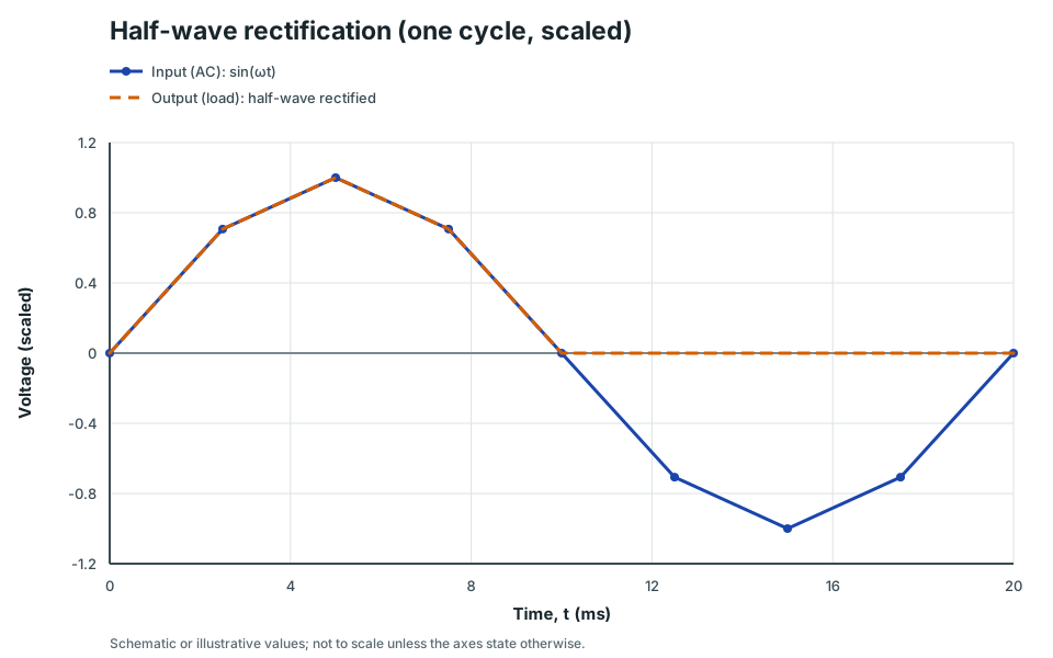
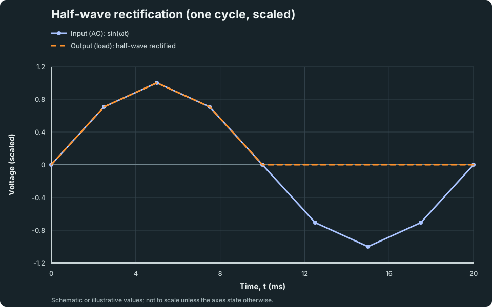
Half-wave rectification (one cycle, scaled)
One cycle of a sinusoidal input and the half-wave rectified output across the load (ideal diode).
Scroll across the graph to read all labels.
View figure data
| Time, t (ms) | Input (AC): sin(ωt) | Output (load): half-wave rectified |
|---|---|---|
| 0 | 0 | 0 |
| 2.5 | 0.707 | 0.707 |
| 5 | 1 | 1 |
| 7.5 | 0.707 | 0.707 |
| 10 | 0 | 0 |
| 12.5 | -0.707 | 0 |
| 15 | -1 | 0 |
| 17.5 | -0.707 | 0 |
| 20 | 0 | 0 |
4. Common Mistakes
- Mixing up forward bias and reverse bias.
- Saying “it becomes d.c.” without stating “pulsating d.c.”.
- Forgetting the load voltage is near zero during the blocked half-cycle (ideal diode model).
5. Exam Tips
- Use the ideal diode model unless the question gives a diode drop.
- State clearly which half-cycle the diode conducts (based on diode orientation).
- Use r.m.s. values only when the question explicitly asks for mean power or r.m.s.; rectified waveforms are not sinusoidal.
- Do not apply Vᵣₘₛ = V₀/square root of 2 to a half-wave output; that shortcut describes a complete sinusoid.
Use the AC Waveform & Power Explorer to move a phase cursor across the input and ideal half-wave output.
Use the Semiconductor Devices Lab to connect forward and reverse bias to half-wave and full-wave current paths.
6. Worked Examples
Modelled example 1
Which half-cycle conducts?
Problem
Study the worked solution
Trace the forward-biased half-cycle
Method
The diode conducts and current flows through the load in one direction.Reason
Forward bias permits conventional current through the diode.Working
Forward bias: I_load follows the conducting half-cycle.Trace the reverse-biased half-cycle
Method
The load current is approximately zero.Reason
The reverse-biased diode blocks the series path.Working
Reverse bias: I_load ≈ 0.Classify the output
Method
Call the load current pulsating d.c.Reason
It is unidirectional but falls to zero for half of every cycle.Working
Output: one unidirectional current pulse per cycle.
Guided practice 2
Peak value at the load (ideal diode)
Problem
Try this before viewing the solution
Hints
Hint 1: conducting model
Hint 2: ideal voltage drop
View solution step by step
Apply the ideal-diode model
Method
Assign zero voltage across the conducting diode.Reason
An ideal diode has no forward voltage drop.Working
V_(load,peak) = V₀-0State the peak
Method
Obtain 12 V.Reason
The entire input peak appears across the resistive load.Working
V_(load,peak) = 12 V.
Common misconception 3
Peak load voltage with a diode drop
Learner claim
Try this before viewing the solution
View solution step by step
Use the stated diode model
Method
Subtract the forward drop from the source peak.Reason
During conduction, Kirchhoff’s voltage law gives V₀ = V_diode + V_load.Working
V_(load,peak) = 10-0.70Evaluate
Method
Obtain 9.3 V.Reason
The diode is explicitly non-ideal in this question.Working
V_(load,peak) = 9.3 V.
Examiner practice 4
Peak current in the load
Examination question
Try this before viewing the solution
View solution step by step
Apply Ohm's law at the peak
1 markMethod
Use Iₚₑₐₖ = Vₚₑₐₖ/R.Reason
The conducting diode places the resistive load across the rectified source.Working
Iₚₑₐₖ = 12/200Evaluate
1 markMethod
Obtain 0.060 A.Reason
The voltage and resistance are in SI units.Working
Iₚₑₐₖ = 0.060 A.Describe the blocked half-cycle
1 markMethod
State I ≈ 0.Reason
The reverse-biased diode opens the series current path.Working
Blocked half-cycle: I_load ≈ 0.
Self-mark with the mark scheme
Compare your response with each mark point. Select a point only when your response contains that evidence.
Self-mark relation, value and blocked-state explanation.
Challenge 5
Peak voltage from an r.m.s. input
Independent transfer
Try this before viewing the solution
Hints
Hint 1: convert the input representation
View solution step by step
Convert the sinusoidal input to peak
Method
Multiply its r.m.s. value by square root of 2.Reason
The supplied input is a complete sinusoid.Working
V₀ = square root of 2 (6.0) = 8.49 VApply ideal rectification
Method
Assign 8.49 V as the conducting load peak.Reason
The ideal diode has zero forward drop.Working
V_(load,peak) = 8.49 V.Describe the output
Method
Retain one sinusoidal half-cycle and set the opposite half-cycle to zero.Reason
The diode alternates between forward and reverse bias.Working
Conducting half-cycle: sinusoidal pulse; blocked half-cycle: V_load = 0.
7. Mind Stretchers
Mind stretcher 1: Pulse repetition rate (half-wave)Extension
If the input frequency is 50 Hz, what is the repetition rate of the pulses in half-wave rectification? Explain.
Show Answer
Half-wave rectification produces one pulse per input cycle, so the pulse repetition rate is 50 Hz.
Mind stretcher 2: Reversing the diodeExtension
Describe what happens to the output if the diode is reversed.
Show Answer
The diode would conduct on the opposite half-cycle, so the output pulses would flip polarity (still pulsating d.c., but of the opposite sign across the load).
Continue with the next resource in this course.
Course and syllabus information
- Course
- GCE A-Level H2 Physics
- Edition
- GCE A-Level H2 Physics 2027