Inductance
Key idea: Learn self-inductance and mutual inductance, use V = L dI/dt, and combine inductors in series/parallel with worked examples.
Continue where you stopped
The core idea
On this page
Learning objectives
- define self-inductance as the ratio of the e.m.f. induced in an electrical circuit / component to the rate of dI change of current causing it and use V = L to solve problems dt
- show an understanding that mutual inductance is the tendency of an electrical circuit / component to oppose a change in the current in a nearby electrical circuit / component
An inductor opposes changes in current. When its current changes, self-induction produces an e.m.f. whose direction opposes that change. In magnitude, |E_L| = L|dI/dt|
1. Definitions (Must Know)
- Self-inductance, L (H): the ratio of the magnitude of the induced e.m.f. in a circuit or component to the magnitude of the rate of change of current producing it.
- Induced e.m.f. across an inductor (magnitude): V = L|dI/dt| (use the sign convention in circuit equations to show “opposes the change”.)
- Mutual inductance (qualitative): a changing current in one circuit changes the magnetic flux linking a nearby circuit and induces an e.m.f. there. Its direction is set by Lenz’s law.
- Unit: 1 H = 1 V s A⁻¹.
- Symbols used in this lesson: L (H), V (V), I (A), t (s), M mutual inductance (H).
2. Key Ideas (What Earns Marks)
- Inductors oppose changes in current, not steady current. If dI/dt = 0, then V = 0 across an ideal inductor.
- Bigger L means a bigger induced e.m.f. for the same dI/dt.
- For ideal, uncoupled inductors, the combination rules match resistor rules:
- series: add directly,
- parallel: add reciprocals.
Quick reference:
| Setup | Key result | When to use |
|---|---|---|
| Ideal inductor | V = LdI/dt | Transients / changing current |
| Steady current | dI/dt = 0 ⇒ V = 0 | Long time after switching |
| Inductors in series | L_eq = L₁ + L₂ + … | Same current through each |
| Inductors in parallel | 1/L_eq = 1/L₁ + 1/L₂ + … | Same voltage across each |
Self-inductance and mutual inductance
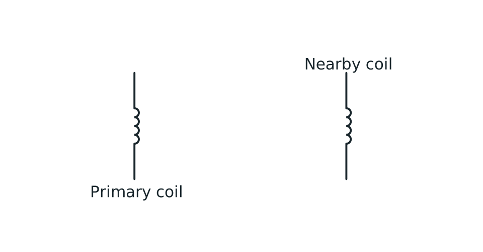
Two separate coils are shown side by side. A labelled arrow shows changing current in the primary. Two labelled curved arrows show changing magnetic flux linking both coils, and an arrow at the secondary identifies the induced effect.

View figure data
| Part | Meaning |
|---|---|
| Primary coil | Changing current I₁ produces changing magnetic flux and a self-induced e.m.f. |
| Magnetic link | Changing flux links the primary and nearby secondary coil |
| Secondary coil | The linked changing flux produces a mutually induced e.m.f. |
3. Detailed Explanations
A. What V = LdI/dt means physically
If the current is increasing, the induced e.m.f. acts to oppose the increase (it acts like a “back e.m.f.”). If the current is decreasing, the induced e.m.f. acts to oppose the decrease (it “supports” the current).
That is why inductors smooth current changes in transient circuits.
B. Series and parallel inductors
For inductors in series: L_eq = L₁ + L₂ + …
For inductors in parallel: 1/L_eq = 1/L₁ + 1/L₂ + …
These relations are examinable in H3 and apply when mutual magnetic coupling between the inductors is negligible. Coupled coils require extra mutual-inductance terms.
C. Mutual inductance (what you need to know)
If current in coil 1 changes, coil 2 experiences an induced e.m.f. The syllabus only requires a qualitative understanding: this induced effect tends to oppose the change that caused it.
The syllabus requires this effect qualitatively. Unless a question supplies an additional model, do not assume a numerical mutual-inductance equation is needed.
4. Common Mistakes
- Using V = LI (wrong); it is proportional to dI/dt, not I.
- Forgetting that L is in henries (H), not ohms.
- Treating the inductor as a “voltage source” with a fixed e.m.f.; the induced e.m.f. depends on how fast the current changes.
- Mixing up series/parallel rules (series adds; parallel adds reciprocals).
- Applying the uncoupled combination formulae to coils that share significant magnetic flux.
5. Exam Tips
- Always write the rate of change explicitly: dI/dt ≈ (Δ I)/(Δ t) when data is given.
- If a question says “steady state” (long time after switching), use dI/dt = 0 ⇒ V_L = 0 for an ideal inductor.
- When combining inductors, compute L_eq first, then plug into circuit equations.
6. Worked Examples
Modelled example 1
Induced e.m.f. from a changing current
Problem
Study the worked solution
Find the current gradient
Method
|dI/dt| = 6.0 A s⁻¹.Reason
A uniform change allows the derivative to be found from Δ I/Δ t.Working
|dI/dt| = (3.0-0)/0.50 = 6.0 A s⁻¹Apply self-inductance
Method
|E| = 2.4 V.Reason
The induced-e.m.f. magnitude is L|dI/dt|.Working
|E| = (0.40)(6.0) = 2.4 V
Guided practice 2
Equivalent inductance (series)
Problem
Try this before viewing the solution
Hints
Hint 1: same branch current
View solution step by step
Add the inductances
Method
L_eq = 0.70 H.Reason
The same current passes through both series components and mutual coupling is excluded.Working
L_eq = 0.20 + 0.50 = 0.70 H
Common misconception 3
Equivalent inductance (parallel)
Learner claim
Try this before viewing the solution
View solution step by step
Use the parallel rule
Method
1/L_eq = 5.00 H⁻¹.Reason
The same voltage appears across both parallel branches.Working
1/L_eq = 1/0.30 + 1/0.60 = 5.00Invert
Method
L_eq = 0.20 H.Reason
The equivalent is the reciprocal of the summed reciprocal.Working
L_eq = 1/5.00 = 0.20 H
Examiner practice 4
Steady current means zero inductor voltage
Examination question
Try this before viewing the solution
View solution step by step
Interpret steady
1 markMethod
dI/dt = 0.Reason
Steady current is constant in time.Working
I = constantCalculate voltage
1 markMethod
V_L = 0 V.Reason
An ideal inductor responds to current change, not current magnitude.Working
V_L = L(dI/dt) = (0.80)(0) = 0State the distinction
1 markMethod
A non-zero steady current can flow with zero ideal-inductor voltage.Reason
V = LI is not the inductance law.Working
I ≠ 0, dI/dt = 0
Self-mark with the mark scheme
Compare your response with each mark point. Select a point only when your response contains that evidence.
Self-mark the steady-current derivative, voltage and explanation.
Challenge 5
Mutual inductance reasoning
Independent transfer
Try this before viewing the solution
Hints
Hint 1: follow the causal chain
View solution step by step
Identify the changing quantity
Method
The increasing primary current changes the magnetic field and linked flux through coil 2.Reason
Only changing linked flux induces an e.m.f.Working
dI₁/dt ≠ 0 ⇒ dΦ₂/dt ≠ 0Apply induction
Method
Faraday induction produces an e.m.f. in coil 2.Reason
The secondary loop experiences changing magnetic flux.Working
E₂ ∝ -dΦ₂/dtSet direction
Method
Any resulting current opposes the linked-flux change.Reason
Lenz’s law determines the opposition; terminal polarity also depends on winding orientation.Working
induced effect opposes the cause
7. Mind Stretchers
Mind stretcher 1: “Opposes the change” but current still changesExtension
An RL circuit is switched on. The current starts at 0 and rises towards a final value.
If the inductor “opposes changes in current”, why does the current change at all?
Answer
The inductor’s induced e.m.f. opposes the change, but the source e.m.f. provides a net driving effect. The result is a gradual change rather than an instantaneous jump.
Mind stretcher 2: Why parallel inductors reduce the equivalent inductanceExtension
Resistors in parallel give a smaller R_eq. Inductors in parallel also give a smaller L_eq.
Give a short physical intuition for why putting inductors in parallel makes the overall circuit “less inductive”.
One good intuition
In parallel, the same applied voltage is shared across each inductor, but the current can split between branches. For a given rate of change of total current, the induced voltage needed can be smaller because each branch can contribute part of the changing current, so the effective opposition to change (inductance) is reduced.
8. Optional/Enrichment: Flux Linkage (Only If Given)
Some treatments define self-inductance via flux linkage λ = NΦ and L = λ/I. You do not need this formalism unless a question explicitly introduces it.
Next step
Continue to Dielectrics and Ferromagnetic Materials for the qualitative material limits that affect real capacitors and inductors.
Continue with the next resource in this course.
Course and syllabus information
- Course
- GCE A-Level H3 Physics
- Edition
- GCE A-Level H3 Physics 2027