Dielectrics and Ferromagnetic Materials
Key idea: Qualitative H3 guide to how dielectrics affect capacitance and breakdown, and how ferromagnetic cores affect inductance, non-linearity, and saturation.
Continue where you stopped
The core idea
On this page
Learning objectives
- show a qualitative understanding that dielectric materials enhance capacitance, and that dielectric breakdown can occur when the electric field is sufficiently strong (knowledge of the quantitative modification of electric fields in matter through the permittivity is not required)
- show a qualitative understanding that ferromagnetic materials enhance inductance and that this enhancement is non-linear especially near saturation (knowledge of the quantitative modification of magnetic fields in matter through the permeability is not required)
Materials can strongly change how capacitors and inductors behave:
- dielectrics increase capacitance (until breakdown), and
- ferromagnetic materials increase inductance, but often non-linearly (especially near saturation).
This lesson is deliberately qualitative to match the H3 syllabus scope.
1. Definitions (Must Know)
- Dielectric: an insulating material that can be polarised in an electric field.
- Dielectric breakdown: failure of the insulating property when the electric field is sufficiently strong, causing a large conduction current (often destructive).
- Ferromagnetic material: material with strong magnetic response due to domain alignment (e.g. iron); commonly used as a core to increase inductance.
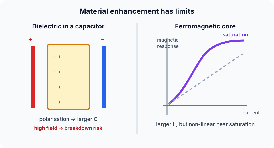
- Saturation (ferromagnetics): a regime where increasing current produces diminishing increases in magnetic response (non-linear behaviour).
- Symbols used in this lesson: C capacitance (F), V potential difference (V), Q charge (C), E electric field strength (V m⁻¹), L inductance (H), I current (A), R resistance (Ω), τ time constant (s), E e.m.f. (V).
2. Key Ideas (What Earns Marks)
- Dielectrics increase capacitance: for the same geometry, inserting a dielectric makes a capacitor store more charge per volt.
- Strong fields can cause dielectric breakdown, so “better capacitor” has a safety limit.
- Ferromagnetic cores increase inductance by strengthening the magnetic field for a given current.
- The inductance enhancement is non-linear, especially as the core approaches saturation.
3. Detailed Explanations
A. Dielectrics: why capacitance increases (qualitative)
When a dielectric is placed between capacitor plates, charges in the dielectric shift slightly (polarisation). This creates an internal field that partially opposes the applied field.
Consequences (qualitative):
- for a given applied charge, the potential difference is reduced, so C = Q/V increases, or
- for a given applied voltage, the capacitor can hold more charge.
B. Dielectric breakdown (what it means in circuits)
If the electric field in the dielectric becomes too large, the dielectric can ionise and become conducting. The capacitor then:
- leaks current heavily,
- may heat up rapidly, and
- may be damaged permanently.
In exam terms: “breakdown means the dielectric no longer insulates once E is sufficiently strong.”
C. Ferromagnetic cores: why inductance increases (qualitative)
Inductors store energy in magnetic fields. A ferromagnetic core increases the magnetic response so that, for the same current, the magnetic field and flux linkage are larger. This makes the inductor “more inductive” (greater opposition to current change).
D. Why the enhancement is non-linear (saturation)
At low fields, magnetic domains align readily, giving a large increase in inductance compared with an air core.
As the core approaches saturation, fewer domains remain to align, so:
- further increases in current produce smaller increases in magnetic response,
- the effective inductance can drop and become current-dependent.
This is why a constant-L model may fail at high currents.
4. Common Mistakes
- Treating dielectric insertion as “always safe” (ignoring breakdown).
- Thinking “higher inductance” from a ferromagnetic core is constant for all currents (ignoring saturation).
- Mixing up dielectric (electric field / capacitor) vs ferromagnetic core (magnetic field / inductor).
5. Exam Tips
- If asked “why does C increase?”, mention polarisation reduces effective field / reduces V for the same Q.
- If asked “why is it non-linear?”, mention domain alignment + saturation.
- If a question hints “strong field” or “high voltage”, mention breakdown risk.
6. Worked Examples
Modelled example 1
Qualitative: inserting a dielectric
Problem
Study the worked solution
Fix the controlled quantity
Method
The battery keeps V fixed.Reason
It can transfer charge to or from the plates.Working
V = constantApply the material effect
Method
Capacitance increases.Reason
Polarisation reduces the field produced per unit free charge.Working
C↑Infer charge
Method
Stored free charge increases.Reason
Q = CV with fixed V.Working
C↑, V fixed ⇒ Q↑
Guided practice 2
Qualitative: ferromagnetic core and saturation
Problem
Try this before viewing the solution
Hints
Hint 1: track incremental response
View solution step by step
Identify the non-linearity
Method
The core’s flux response ceases to scale linearly with current.Reason
Magnetic domains are approaching alignment saturation.Working
ΔΦ/Δ I decreasesInfer inductance
Method
Effective incremental inductance becomes current-dependent and often decreases.Reason
Inductance measures flux-linkage response to current change.Working
L_effnot = constant
Common misconception 3
Capacitor disconnected (fixed charge case)
Learner claim
Try this before viewing the solution
View solution step by step
Set the boundary condition
Method
Free plate charge stays approximately fixed.Reason
The battery is no longer connected.Working
Q = constantApply dielectric effect
Method
C increases.Reason
The inserted dielectric polarises.Working
C↑Infer voltage
Method
V decreases.Reason
V = Q/C with fixed Q.Working
C↑, Q fixed ⇒ V↓
Examiner practice 4
Breakdown risk check (qualitative)
Examination question
Try this before viewing the solution
View solution step by step
Relate field to voltage
1 markMethod
E ≈ V/d.Reason
The field is approximately uniform between parallel plates.Working
d = constantInfer field change
1 markMethod
Field strength increases.Reason
V rises while d stays fixed.Working
V↑ ⇒ E↑Name failure
1 markMethod
Dielectric breakdown can occur.Reason
The material’s maximum sustainable field is exceeded.Working
E > E_breakdownDescribe consequence
1 markMethod
The material ionises, conducts heavily and heats.Reason
The insulating state collapses and may fail catastrophically.Working
insulator → conducting path
Self-mark with the mark scheme
Compare your response with each mark point. Select a point only when your response contains that evidence.
Self-mark relation, field trend, named failure and consequence.
Challenge 5
Why a core can change RL transient behaviour (qualitative)
Independent transfer
Try this before viewing the solution
Hints
Hint 1: link the two models
View solution step by step
Apply saturation
Method
Effective incremental L can decrease as current rises.Reason
The core adds progressively less flux response.Working
I↑ ⇒ L_eff↓Infer time constant
Method
τ_eff decreases for fixed R.Reason
τ = L/R.Working
L_eff↓ ⇒ τ_eff↓Infer transient shape
Method
Current can rise faster than the ideal constant-L exponential predicts.Reason
The circuit becomes less inductive as saturation develops.Working
non-linear current growth
7. Mind Stretchers
Mind stretcher 1: Why “breakdown” is not just a bigger leakage currentExtension
Why can dielectric breakdown be catastrophic rather than a small, reversible effect?
Answer
Once breakdown starts, current can rise sharply, causing rapid heating and damage (carbonisation, melting, permanent conductive paths), so the capacitor may fail permanently rather than just “leak a bit more”.
Mind stretcher 2: Why high-C and high-V together are hardExtension
Dielectrics can increase capacitance and also have a maximum field strength before breakdown. Explain why building a capacitor that is both very high capacitance and very high voltage rating is challenging.
Answer
To get high capacitance you typically want small plate separation and a strong dielectric effect, but small separation and high voltage both increase the electric field strength E, pushing the dielectric toward breakdown. Engineering a material/geometry that supports high C while keeping E safely below breakdown is the challenge.
8. Optional/Enrichment: Permittivity and Permeability (Quantitative)
The H3 syllabus does not require quantitative modification of fields in matter via permittivity or permeability. For a deeper quantitative model, see Dielectrics in Capacitors.
Practical circuit work often uses data-sheet parameters (e.g. dielectric strength, saturation current) rather than first-principles field calculations.
Next step
Continue to Energy in an Inductor to derive the magnetic energy stored as current builds.
Continue with the next resource in this course.
Course and syllabus information
- Course
- GCE A-Level H3 Physics
- Edition
- GCE A-Level H3 Physics 2027