RL Circuits
Key idea: Solve RL transient problems using the time constant τ = L/R, current growth/decay equations, and exam-style worked examples.
Continue where you stopped
The core idea
On this page
Learning objectives
- define self-inductance as the ratio of the e.m.f. induced in an electrical circuit / component to the rate of dI change of current causing it and use V = L to solve problems dt
- show an understanding that mutual inductance is the tendency of an electrical circuit / component to oppose a change in the current in a nearby electrical circuit / component
- show a qualitative understanding that dielectric materials enhance capacitance, and that dielectric breakdown can occur when the electric field is sufficiently strong (knowledge of the quantitative modification of electric fields in matter through the permittivity is not required)
- show a qualitative understanding that ferromagnetic materials enhance inductance and that this enhancement is non-linear especially near saturation (knowledge of the quantitative modification of magnetic fields in matter through the permeability is not required)
- Apply U = ½LI² to the energy stored in an inductor.
- Derive the expression U = ½LI² for the potential energy stored in an inductor by considering the work done on charges.
- solve problems using the formulae for the combined inductance of two or more inductors in series and in parallel
- solve problems involving circuits with resistors, inductors, and sources of constant e.m.f. (includes solving first-order differential equations) [RL series circuits with constant e.m.f. source]
- solve problems involving circuits with inductors and capacitors only (includes solving second-order differential equations) [LC series circuits without e.m.f. source]
- solve problems involving circuits with resistors, inductors and capacitors only (candidates are not expected to solve the general second-order differential equations, though they can be asked to verify and use particular solutions). [RLC series circuits without e.m.f. source]
An RL series circuit has a resistor R and ideal inductor L connected to a constant e.m.f. source E. Take current around the loop as positive. When the switch changes, the inductor current cannot jump instantaneously; the result is a first-order transient with time constant: τ = L/R
1. Definitions (Must Know)
- Inductor voltage: V_L = LdI/dt (sign depends on convention; it opposes the change).
- Resistor voltage: V_R = IR
- Time constant (RL): τ = L/R (s).
- Steady state (long time after switch): dI/dt = 0 ⇒ V_L = 0 (ideal inductor behaves like a wire).
- Symbols used in this lesson: E (V), R (Ω), L (H), I (A), t (s), τ (s).
2. Key Ideas (What Earns Marks)
- Current continuity: in an ideal inductor, current cannot change instantaneously.
- Use KVL with the inductor term to get the differential equation.
- For a step to constant E (switch on): I(t) = (E/R)(1-e^(-t/τ))
- For current decay after removing the source (switch off, RL loop): I(t) = I₀ e^(-t/τ)
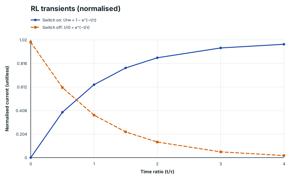
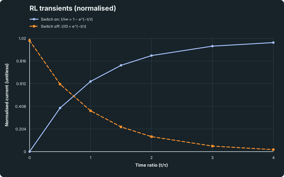
RL transients (normalised)
Current grows toward its final value on switching on, and decays exponentially on switching off; both are governed by the same time constant τ = L/R.
Scroll across the graph to read all labels.
View figure data
| Time ratio (t/τ) | Switch on: I/I∞ = 1 − e^(−t/τ) | Switch off: I/I0 = e^(−t/τ) |
|---|---|---|
| 0 | 0 | 1 |
| 0.5 | 0.393 | 0.607 |
| 1 | 0.632 | 0.368 |
| 1.5 | 0.777 | 0.223 |
| 2 | 0.865 | 0.135 |
| 3 | 0.95 | 0.05 |
| 4 | 0.982 | 0.018 |
3. Detailed Explanations
A. Switching on (current growth): setting up the ODE
Apply Kirchhoff’s voltage law around the loop: E = IR + LdI/dt Rearrange: dI/dt + (R/L)I = E/L This is a first-order linear differential equation.
B. Solving (standard result)
The solution that satisfies I(0) = 0 is: I(t) = (E/R)(1-e^(-(R/L)t))
Using τ = L/R, I(t) = (E/R)(1-e^(-t/τ)). Key checkpoints:
- t = 0 ⇒ I = 0
- t → ∞ ⇒ I → E/R
- initial slope: .dI/dt|ₜ₌₀ = E/L
C. Switching off (current decay)
If the source is removed but R and L remain in a closed loop, KVL gives: 0 = IR + LdI/dt So: dI/dt = -(R/L)I Solution: I(t) = I₀ e^(-t/τ)
4. Common Mistakes
- Treating the inductor like a resistor: using V_L = IL (wrong).
- Assuming current instantly becomes E/R at t = 0 (it starts at 0 and rises).
- Forgetting steady-state behaviour: at long times, V_L = 0 for an ideal inductor.
- Mixing up τ = L/R with RC time constants from capacitors.
5. Exam Tips
-
Write KVL first, then identify the form “L dI/dt + RI = E”.
-
If asked for time to reach a fraction of final current: I/I_∞ = 1-e^(-t/τ)
Rearranging gives t = -τ ln(1-I/I_∞).
-
At t = τ, I reaches 1-e⁻¹ ≈ 0.632 of its final value.
6. Worked Examples
Modelled example 1
Current growth at a given time
Problem
Study the worked solution
Find the circuit scales
Method
τ = 0.50 s and I_∞ = 3.0 A.Reason
τ = L/R sets the growth rate and E/R is the steady current.Working
τ = 2.0/4.0 = 0.50 s, I_∞ = 12/4.0 = 3.0 AEvaluate the growth law
Method
I = 1.9 A.Reason
At t = τ, the growth factor is 1-e⁻¹.Working
I = 3.0(1-e⁻¹) = 1.9 A
Guided practice 2
Time to reach 90% of final current
Problem
Try this before viewing the solution
Hints
Hint 1: isolate the exponential
View solution step by step
Isolate the decay factor
Method
e^(-t/τ) = 0.10.Reason
The remaining gap to the final current is ten percent.Working
0.90 = 1-e^(-t/τ)Take logarithms
Method
t = 1.2 s.Reason
t = τ ln 10 with τ = 0.50 s.Working
t = (0.50)(2.303) = 1.2 s
Common misconception 3
Current decay
Learner claim
Try this before viewing the solution
View solution step by step
Find the time constant
Method
τ = 0.50 s.Reason
τ = L/R.Working
τ = 1.5/3.0 = 0.50 sUse decay from the initial value
Method
I = 0.27 A.Reason
The source-free current approaches zero.Working
I = 2.0e^(-1.0/0.50) = 0.27 A
Examiner practice 4
Inductor voltage during current growth
Examination question
Try this before viewing the solution
View solution step by step
State current growth
1 markMethod
I = (E/R)(1-e^(-t/τ)).Reason
This is the switch-on solution.Working
τ = L/RDifferentiate
1 markMethod
dI/dt = (E/L)e^(-t/τ).Reason
Differentiating converts Rτ to L.Working
dI/dt = (E/L)e^(-t/τ)Relate voltage
1 markMethod
|V_L| = E e^(-t/τ).Reason
|V_L| = L|dI/dt|.Working
|V_L| = L(E/L)e^(-t/τ)Evaluate
1 markMethod
|V_L| = 4.4 V.Reason
t = τ = 0.50 s.Working
|V_L| = 12e⁻¹ = 4.4 V
Self-mark with the mark scheme
Compare your response with each mark point. Select a point only when your response contains that evidence.
Self-mark growth law, derivative, voltage relation and value.
Challenge 5
Energy stored at a given time (link to inductor energy)
Independent transfer
Try this before viewing the solution
Hints
Hint 1: retain the unrounded current
View solution step by step
Use instantaneous current
Method
I = 3.0(1-e⁻¹) A.Reason
Stored energy depends on the current at that instant.Working
I = I_∞(1-e^(-t/τ))Calculate energy
Method
U = 3.6 J.Reason
Substitute the unrounded current into U = (1/2)LI².Working
U = (1/2)(2.0)[3.0(1-e⁻¹)]² = 3.6 J
7. Mind Stretchers
Mind stretcher 1: Why the inductor voltage can exceed the source voltageExtension
When switching off, why can the induced voltage across the inductor become very large?
Answer
Because V_L = L dI/dt. If the circuit tries to force the current to drop very quickly (large negative dI/dt), the inductor generates a large induced e.m.f. to oppose that rapid change. This is why sparks can occur at switches.
Mind stretcher 2: Which is continuous: current or voltage?Extension
At the instant a switch is toggled in an ideal RL circuit, which quantity is continuous and which can change abruptly: the current through the inductor or the voltage across it? Explain briefly.
Answer
The inductor current is continuous (it cannot change instantaneously). The inductor voltage can change abruptly because V_L = L dI/dt and the derivative can change at the switching instant depending on the circuit conditions.
8. Optional/Enrichment: Non-ideal Inductors
Real inductors have internal resistance and can saturate (with ferromagnetic cores). These effects modify the transient behaviour, but H3 RL questions typically model inductors as ideal unless stated otherwise.
Next step
Continue to LC Circuits, where a capacitor and inductor exchange energy in a second-order oscillation.
Continue with the next resource in this course.
Course and syllabus information
- Course
- GCE A-Level H3 Physics
- Edition
- GCE A-Level H3 Physics 2027