LC Circuits
Key idea: Derive the LC oscillator equation, use ω = 1/√(LC) and T = 2π√(LC), and solve charge/current/energy questions with examples.
Continue where you stopped
The core idea
On this page
Learning objectives
- define self-inductance as the ratio of the e.m.f. induced in an electrical circuit / component to the rate of dI change of current causing it and use V = L to solve problems dt
- show an understanding that mutual inductance is the tendency of an electrical circuit / component to oppose a change in the current in a nearby electrical circuit / component
- show a qualitative understanding that dielectric materials enhance capacitance, and that dielectric breakdown can occur when the electric field is sufficiently strong (knowledge of the quantitative modification of electric fields in matter through the permittivity is not required)
- show a qualitative understanding that ferromagnetic materials enhance inductance and that this enhancement is non-linear especially near saturation (knowledge of the quantitative modification of magnetic fields in matter through the permeability is not required)
- Apply U = ½LI² to the energy stored in an inductor.
- Derive the expression U = ½LI² for the potential energy stored in an inductor by considering the work done on charges.
- solve problems using the formulae for the combined inductance of two or more inductors in series and in parallel
- solve problems involving circuits with resistors, inductors, and sources of constant e.m.f. (includes solving first-order differential equations) [RL series circuits with constant e.m.f. source]
- solve problems involving circuits with inductors and capacitors only (includes solving second-order differential equations) [LC series circuits without e.m.f. source]
- solve problems involving circuits with resistors, inductors and capacitors only (candidates are not expected to solve the general second-order differential equations, though they can be asked to verify and use particular solutions). [RLC series circuits without e.m.f. source]
An LC series circuit (no resistor, no e.m.f. source) can undergo electromagnetic oscillations: energy swaps between the capacitor’s electric field and the inductor’s magnetic field. Mathematically, it behaves like SHM with angular frequency: ω = 1/(square root of LC)
1. Definitions (Must Know)
- Capacitor charge: q(t) (C).
- Current convention: choose positive current so that I(t) = dq/dt, where q is the charge on the selected capacitor plate.
- Capacitor voltage: V_C = q/C
- Inductor voltage: V_L = LdI/dt = Ld²q/dt²
- Natural (angular) frequency (LC): ω = 1/(square root of LC)
- Period: T = 2π/ω = 2π square root of LC
- Symbols used in this lesson: L (H), C (F), q (C), Q maximum charge (C), I (A), Iₘₐₓ maximum current (A), t (s), ω (rad s⁻¹), T (s), U_C (J), U_L (J).
2. Key Ideas (What Earns Marks)
-
In an ideal LC circuit, the total energy is conserved: U = q²/2C + 1/2 LI² = constant
-
KVL gives a second-order ODE for q(t) that matches SHM: d²q/dt² + (1/LC)q = 0
-
Solutions are sinusoidal: q(t) = Q cos(ω t + φ)
I(t) = -ω Q sin(ω t + φ)
3. Detailed Explanations
A. Deriving the LC differential equation (no source)
Apply KVL around the loop (sign convention consistent): V_L + V_C = 0 Substitute: Ld²q/dt² + q/C = 0 Divide by L: d²q/dt² + (1/LC)q = 0 Compare with SHM form x double dot + ω² x = 0, so: ω² = 1/LC ⇒ ω = 1/(square root of LC)
B. What oscillates (and what is out of phase)
- q(t) and V_C(t) are in phase (since V_C = q/C).
- I(t) = dq/dt is π/2 out of phase with q(t).
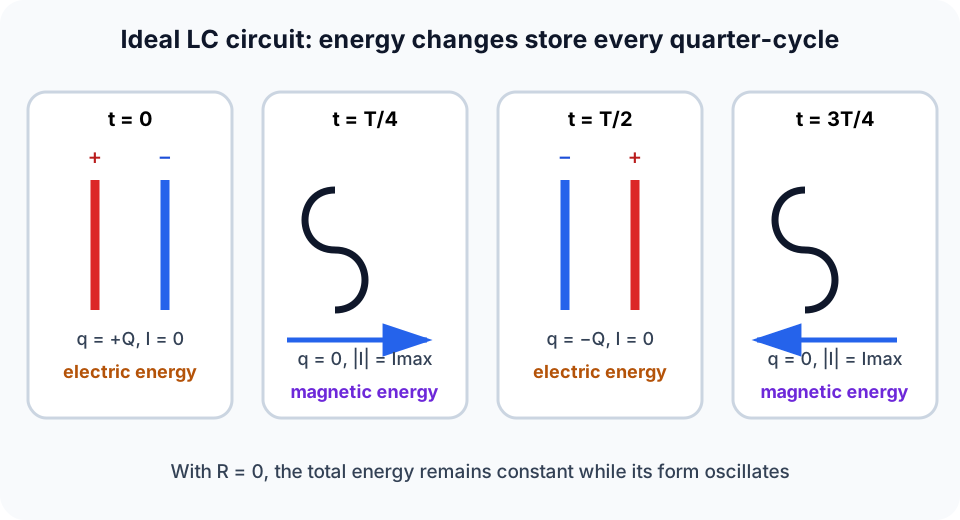
- Energy swaps:
- capacitor energy: U_C = (1/2)q²/C
- inductor energy: U_L = 1/2 LI² When q is maximum, I = 0 (energy purely in capacitor). When I is maximum, q = 0 (energy purely in inductor).
4. Common Mistakes
- Forgetting I = dq/dt and writing I = q/t.
- Using V_C = CV (wrong); it is V_C = q/C.
- Dropping the second derivative: LC circuits require d²q/dt².
- Treating the oscillations as decaying without a resistor (ideal LC does not decay).
5. Exam Tips
- Start from KVL and decide your state variable (q is usually cleanest).
- Quote ω = 1/square root of LC and T = 2π square root of LC once you recognise “ideal LC”.
- Use phase reasoning: “current leads charge by 90°” (or “I is derivative of q”).
6. Worked Examples
Modelled example 1
Find the natural frequency and period
Problem
Study the worked solution
Find the LC time scale
Method
square root of LC = 2.0 × 10⁻³ s.Reason
Convert microfarads before multiplying.Working
square root of ((0.50)(8.0 × 10⁻⁶)) = 2.0 × 10⁻³ sFind angular frequency
Method
ω = 500 rad s⁻¹.Reason
ω = 1/square root of LC.Working
ω = 1/(2.0 × 10⁻³) = 500 rad s⁻¹Find period
Method
T = 1.3 × 10⁻² s.Reason
T = 2π/ω.Working
T = 2π(2.0 × 10⁻³) = 1.3 × 10⁻² s
Guided practice 2
Maximum current from initial charge (energy method)
Problem
Try this before viewing the solution
Hints
Hint 1: compare two extreme states
View solution step by step
Write the initial energy
Method
U = Q²/(2C).Reason
Initially current is zero and capacitor charge is maximum.Working
U_C = Q²/(2C)Write maximum-current energy
Method
U = (1/2)LIₘₐₓ².Reason
At maximum current the ideal capacitor is momentarily uncharged.Working
U_L = (1/2)LIₘₐₓ²Equate and solve
Method
Iₘₐₓ = Q/square root of LC = ω Q.Reason
Total energy is conserved.Working
Q²/(2C) = LIₘₐₓ²/2
Common misconception 3
Find Q from Iₘₐₓ (reverse of Example B)
Learner claim
Try this before viewing the solution
View solution step by step
Find the time scale
Method
square root of LC = 2.0 × 10⁻³ s.Reason
Convert 10 μF to 10 × 10⁻⁶ F.Working
square root of ((0.40)(10 × 10⁻⁶)) = 2.0 × 10⁻³ sRearrange correctly
Method
Q = 3.0 × 10⁻³ C.Reason
Iₘₐₓ = Q/square root of LC implies multiplication by the time scale.Working
Q = (1.5)(2.0 × 10⁻³) = 3.0 × 10⁻³ C
Examiner practice 4
Energy at maximum current
Examination question
Try this before viewing the solution
View solution step by step
Capacitor energy
1 markMethod
U = 0.40 J.Reason
At maximum charge all ideal-circuit energy is electric.Working
U = Q²/(2C) = 0.40 JEquate energies
1 markMethod
(1/2)LIₘₐₓ² = U.Reason
At maximum current all energy is magnetic.Working
Iₘₐₓ = square root of (2U/L)Substitute
1 markMethod
Iₘₐₓ = square root of (2(0.40)/0.20).Reason
Use SI quantities.Working
Iₘₐₓ = square root of 4Report
1 markMethod
Iₘₐₓ = 2.0 A.Reason
Take the positive magnitude.Working
Iₘₐₓ = 2.0 A
Self-mark with the mark scheme
Compare your response with each mark point. Select a point only when your response contains that evidence.
Self-mark capacitor energy, energy equality, substitution and current.
Challenge 5
Phase relationship: when is current maximum?
Independent transfer
Try this before viewing the solution
Hints
Hint 1: differentiate charge
View solution step by step
Find current
Method
I = -ω Q sin(ω t).Reason
Current is the time derivative of capacitor charge.Working
I = dq/dtMaximise magnitude
Method
| sin(ω t)| = 1.Reason
The amplitude factor ω Q is constant.Working
ω t = π/2 first after zeroState the time
Method
t = π/(2ω).Reason
This is one quarter of the oscillation period.Working
t = T/4
7. Mind Stretchers
Mind stretcher 1: Why oscillations need both L and CExtension
Why doesn’t a circuit with only a capacitor (no inductor) “oscillate” once discharged?
Answer
You need an inductor to provide “inertia” for current change (magnetic energy storage). A capacitor alone can store electric energy, but without an inductor there’s no mechanism for current to keep flowing and reverse the charge repeatedly.
Mind stretcher 2: What changes when you add a small resistance?Extension
Real circuits always have some resistance. Compared to an ideal LC circuit, what qualitative changes do you expect if you add a small series resistor?
Answer
You get damping: the oscillations decay in amplitude with time because energy is dissipated as heat in the resistor. The oscillation frequency becomes slightly lower than the ideal 1/square root of LC value.
8. Optional/Enrichment: Real LC circuits (damping)
In practice, resistance is never exactly zero, so real LC oscillations decay. The damped case is treated in the RLC analysis lesson:
Next step
Continue to RLC Circuits Analysis to add resistive energy loss and classify the resulting response.
Continue with the next resource in this course.
Course and syllabus information
- Course
- GCE A-Level H3 Physics
- Edition
- GCE A-Level H3 Physics 2027