Dynamics of Angular Motion
Key idea: Learn torque, moment of inertia, and the rotational form of Newton’s second law, with exam tips and worked examples.
Continue where you stopped
The core idea
On this page
Learning objectives
- show an understanding of and use the terms angular momentum and moment of inertia of a rotating rigid body
- calculate the moment of inertia about an axis for simple bodies by using calculus, the parallel-axis theorem or otherwise (knowledge of the perpendicular-axis theorem and mathematical derivation of the moment of inertia for spheres are not required)
- show an understanding of torque produced by a force relative to a reference point, and apply the principle that torque is related to the rate of change of angular momentum to solve problems, such as those involving point masses, rigid bodies, or bodies with a variable moment of inertia e.g. an ice-skater
Dynamics of angular motion is the forces side of rotation: external torque changes angular momentum. For a rigid body rotating about a fixed axis with constant moment of inertia, the working equation is: ∑τₑₓₜ = Iα
1. Definitions (Must Know)
- Torque (moment of a force), τ (N m): turning effect of a force about a chosen point/axis.
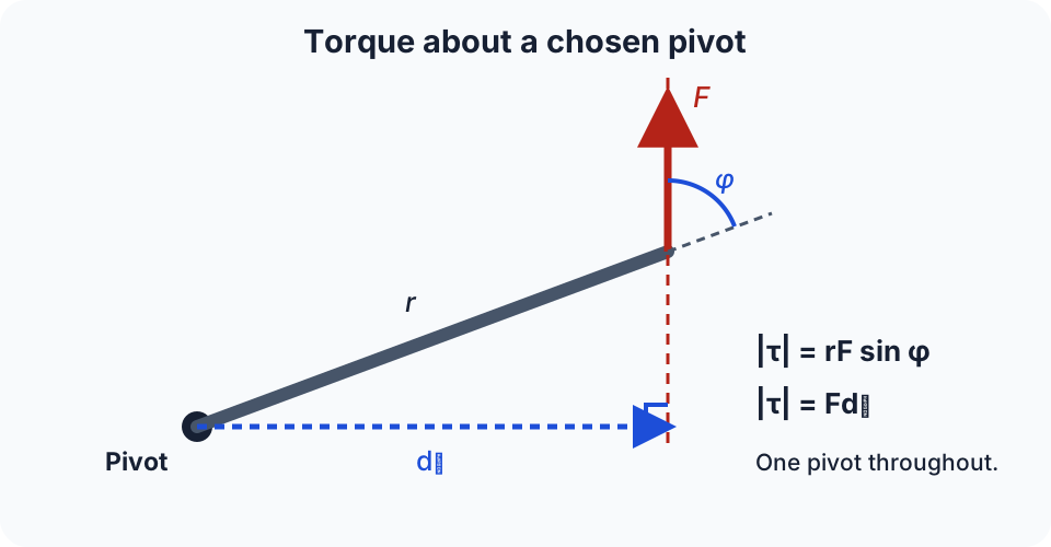
- Magnitude: τ = rF sin φ = Fd_⊥ where r is distance from axis to point of application, φ is the angle between vector r and vector F, and d_⊥ is the perpendicular moment arm.
- Net external torque, ∑τₑₓₜ: the signed sum of external torques about one chosen axis.
- Moment of inertia, I (kg m²): rotational “inertia” about an axis: I = ∑ mᵢrᵢ² for a set of discrete masses.
- Fixed-axis, constant-I form: ∑τₑₓₜ = Iα
- Symbols used in this lesson: τ torque (N m), F force (N), r radius (m), d_⊥ moment arm (m), φ angle (rad), I moment of inertia (kg m²), α angular acceleration (rad s⁻²).
2. Key Ideas (What Earns Marks)
- Always state the axis (or pivot) you’re taking moments about; torque depends on it.
- Use the perpendicular distance: τ = Fd_⊥ is often the safest form.
- I depends on both the mass distribution and the chosen axis.
- For a rigid body about a fixed axis: bigger I means smaller α for the same τₙₑₜ.
Torque formulas (choose the one that matches the diagram):
| Situation | Safe form | Notes |
|---|---|---|
| You know angle to radius | τ = rF sin φ | Use φ between vector r and vector F |
| You know moment arm | τ = Fd_⊥ | d_⊥ is perpendicular distance to the line of action |
3. Detailed Explanations
A. Torque: what matters physically
For a given force magnitude F:
- torque increases if you apply it further from the axis (bigger r),
- torque increases if the force is more perpendicular to the radius (bigger sin φ),
- torque is zero if the line of action passes through the axis (d_⊥ = 0).
B. Obtaining ∑τₑₓₜ = Iα
For a point mass m constrained at distance r from the axis, tangential acceleration is aₜ = rα. Its tangential resultant force is: Fₜ = maₜ = mrα The torque about the axis from this tangential force is: τ = rFₜ = r(mrα) = mr²α
For a rigid body, the general starting point is ∑ vector τₑₓₜ = d vector L/dt. When the body rotates about a fixed axis and I about that axis is constant, L = Iω, so:
This form is not valid unchanged when the rotation axis or moment of inertia varies; use the angular-momentum relation instead.
C. Choosing signs (1D rotation)
Pick a sign convention (e.g. anticlockwise is +). Then:
- torques that tend to rotate the body anticlockwise are positive,
- clockwise torques are negative, and you add them to get τₙₑₜ.
4. Common Mistakes
- Using rF when the force is not perpendicular (should be rF sin φ or Fd_⊥).
- Measuring r to the wrong point (use the distance from axis to where the force acts).
- Mixing torques about different axes in the same equation.
- Writing τ = Iω (incorrect; for a fixed axis and constant I, use ∑τₑₓₜ = Iα).
5. Exam Tips
- Draw the axis/pivot and mark d_⊥; it prevents many sign/geometry errors.
- In multi-force problems, compute each torque separately with its sign, then sum.
- Unit check:
- I in kg m²,
- α in rad s⁻²,
- τ in N m.
6. Worked Examples
Modelled example 1
Torque from a force at an angle
Problem
Study the worked solution
Select the perpendicular component
Method
τ = rF sin φ.Reason
Only force perpendicular to the radius produces torque.Working
F_⊥ = F sin 60°Evaluate
Method
τ = 4.3 N m.Reason
Multiply moment arm by perpendicular force.Working
(0.25)(20) sin 60° = 4.3 N m
Guided practice 2
Using τₙₑₜ = Iα
Problem
Try this before viewing the solution
Hints
Hint 1: rotational second law
View solution step by step
Rearrange
Method
α = τₙₑₜ/I.Reason
Moment of inertia is rotational resistance to angular acceleration.Working
τₙₑₜ = IαEvaluate
Method
α = 4.0 rad s⁻².Reason
Divide torque by inertia.Working
2.0/0.50 = 4.0 rad s⁻²
Common misconception 3
Two torques, one axis
Learner claim
Try this before viewing the solution
View solution step by step
Sum signed torques
Method
τₙₑₜ = +4.0 N m.Reason
The torques act in opposite senses.Working
6.0 + (-2.0) = 4.0Find acceleration
Method
α = +2.0 rad s⁻².Reason
α = τₙₑₜ/I retains the net-torque sign.Working
4.0/2.0 = 2.0 rad s⁻²
Examiner practice 4
Force at a handle (moment arm form)
Examination question
Try this before viewing the solution
View solution step by step
Identify moment arm
1 markMethod
d_⊥ = 0.80 m.Reason
The force is perpendicular.Working
τ = Fd_⊥Calculate torque
1 markMethod
τ = 14.4 N m.Reason
Multiply force by perpendicular distance.Working
(18)(0.80) = 14.4Apply dynamics
1 markMethod
α = τ/I.Reason
Net torque produces angular acceleration.Working
τ = IαReport
1 markMethod
α = 4.0 rad s⁻².Reason
14.4/3.6 = 4.0.Working
4.0 rad s⁻²
Self-mark with the mark scheme
Compare your response with each mark point. Select a point only when your response contains that evidence.
Self-mark moment arm, torque, dynamics relation and acceleration.
Challenge 5
Multiple forces about a pivot (signs)
Independent transfer
Try this before viewing the solution
Hints
Hint 1: assign rotational signs first
View solution step by step
Calculate both torques
Method
τ₁ = +3.0 and τ₂ = -3.0 N m.Reason
They act in opposite senses.Working
τ₁ = (10)(0.30), τ₂ = -(6.0)(0.50)Find net torque
Method
τₙₑₜ = 0.Reason
The equal opposing torques cancel.Working
+ 3.0-3.0 = 0Infer acceleration
Method
α = 0.Reason
α = τₙₑₜ/I.Working
0/0.80 = 0
7. Mind Stretchers
Mind stretcher 1: Same torque, different axisExtension
You apply the same force at the same point on a rigid body, but you choose a different pivot point.
Does the torque change? Explain briefly.
Answer
Yes. Torque depends on the perpendicular distance from the chosen axis/pivot to the line of action of the force, so changing the pivot generally changes d_⊥ and hence τ.
Mind stretcher 2: Can you have motion with zero net torque?Extension
If τₙₑₜ = 0 about an axis, does that guarantee the object is not rotating? Explain.
Answer
No. τₙₑₜ = 0 implies α = 0 (for fixed-axis rotation), so the angular velocity is constant. The object could be at rest (ω = 0) or rotating at a steady rate (ω ≠ 0).
8. Optional/Enrichment: Beyond Fixed-Axis Rotation
If the rotation axis changes direction (3D rigid body rotation) or the frame is non-inertial, you need more advanced tools (e.g. Euler’s equations / rotating-frame dynamics). This is beyond the fixed-axis H3 scope unless explicitly guided by the question.
Next step
Return to the Rotational Motion hub, or continue to the more general Torque and Angular Momentum relation.
Continue with the next resource in this course.
Course and syllabus information
- Course
- GCE A-Level H3 Physics
- Edition
- GCE A-Level H3 Physics 2027