Optical Fibres
Key idea: Advanced Physics: optical fibres — guiding by total internal reflection, step-index, graded-index and single-mode fibres, dispersion, attenuation mechanisms and decibel link budgets.
Continue where you stopped
The core idea
On this page
Learning objectives
- Extend wave optics through polarisation, optical confinement, attenuation, and fibre transport.
Use this page to connect total internal reflection to fibre design, and to keep the two limits on a fibre link apart: dispersion spreads pulses, and attenuation reduces power.
Use this page for:
- core/cladding structure and the acceptance condition,
- step-index, graded-index and single-mode propagation and their dispersion,
- attenuation mechanisms, wavelength windows and decibel link budgets.
Prerequisites: Snell’s law, the critical angle and logarithms.
Fast start
- Guiding needs n_core > n_cladding, so that rays meeting the boundary beyond the critical angle sin θ_c = n_cladding/n_core are totally internally reflected.
- Dispersion spreads a pulse in time and limits the data rate. Attenuation reduces the optical power and limits the distance before amplification or regeneration. They have different causes and different cures.
- Multimode fibres suffer modal dispersion; a graded-index profile reduces it and a single-mode fibre removes it.
- Attenuation comes from absorption, Rayleigh scattering, bending, and splice and connector losses. In silica it is lowest near 1550 nm, not simply at the longest wavelength.
1. Structure and guiding
An optical fibre has a glass core surrounded by a cladding of slightly lower refractive index, protected by a plastic buffer coating. Light entering the end within the fibre’s acceptance cone meets the core–cladding boundary beyond the critical angle and is totally internally reflected, so it stays in the core. The half-angle of the acceptance cone in air is set by the numerical aperture, NA = sin θₘₐₓ = square root of (n₁² - n₂²), where n₁ is the core index and n₂ the cladding index.
2. Modes and dispersion
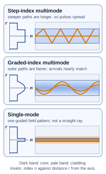
Step-index multimode fibre
The core is wide (typically 50–100 µm) with a uniform index, so many ray paths, or modes, are guided. A steep ray zig-zags and travels further than the axial ray, so parts of one pulse arrive at different times. This modal (intermodal) dispersion broadens pulses. If they overlap, the receiver cannot separate them, so the usable data rate falls as the fibre gets longer.
For a fibre of length L, the axial ray takes t = Ln₁/c. The steepest guided ray, which meets the boundary exactly at the critical angle, travels a path longer by the factor n₁/n₂, so the spread is
Δ t ≈ (Ln₁/c)(n₁/n₂ - 1).
Worked example. For L = 1.0 km, n₁ = 1.48 and n₂ = 1.46: Ln₁/c = 4.93 µs and n₁/n₂ - 1 = 0.0137, so Δ t ≈ 68 ns. Pulses must be spaced by at least this much, so the fibre supports roughly 1/Δ t ≈ 15 million pulses per second over 1 km, and fewer over longer distances.
Graded-index multimode fibre
The core index is highest on the axis and falls gradually towards the cladding. Rays bend back towards the axis instead of reflecting sharply. The longer outer paths run through lower-index glass, where light travels faster, so the arrival times of different modes nearly match. Modal dispersion is greatly reduced, but not eliminated.
Single-mode fibre
The core is only a few micrometres across (typically about 8–10 µm for the 1310 nm and 1550 nm bands), which is small enough that only one mode is guided. That mode is not a single straight ray along the axis. It is a field pattern concentrated in the core that extends slightly into the cladding, as the figure shows. With one mode there is no modal dispersion. What remains is chromatic dispersion: any real source emits a small range of wavelengths, and these travel at slightly different speeds. Single-mode fibre therefore carries the highest data rates over the longest distances. The trade-offs are that its tiny core needs a laser source and precise alignment at joints, whereas multimode fibre accepts cheaper LED sources and is easier to connect.
Try it first. Compare the intermodal pulse spreading in 2 km step-index multimode, graded-index multimode and single-mode fibres. Assume the multimode fibres have comparable core/cladding indices and many excited modes, and the graded-index profile is designed to reduce transit-time differences. Rank their intermodal spreading and explain why a single-mode pulse can still broaden.
Compare your ranking
Step-index multimode has the greatest intermodal spreading in this comparison, because its modes have different transit times. Graded-index multimode has much less, because its index profile nearly equalises those times. Single-mode has no intermodal spreading, but its pulse can still broaden through chromatic dispersion. Ranking total spreading would also require the source bandwidth, wavelength and each fibre’s chromatic dispersion. Attenuation does not belong in this ranking, because a weaker pulse is not a wider one.
3. Attenuation
Attenuation reduces the power without, by itself, changing the pulse shape. Its main causes are:
- Absorption. Silica absorbs strongly in the ultraviolet, through electronic transitions, and increasingly beyond about 1.6 µm in the infrared, through molecular vibrations. Impurities add absorption peaks; residual hydroxyl (OH⁻) ions absorb strongly near 1380 nm.
- Rayleigh scattering from tiny, frozen-in density variations in the glass. It is proportional to 1/λ⁴, so it dominates at shorter wavelengths.
- Bending losses. A tight bend (macrobending) or small kinks from poor cabling (microbending) make rays meet the boundary below the critical angle, so light escapes into the cladding.
- Splice and connector losses. These come from misaligned or mismatched cores and from air gaps. At an air gap, part of the light is reflected at each surface. Of the power arriving at a surface, the fractions reflected (R), transmitted (T) and absorbed (A) satisfy R + T + A = 1, counting only the light at that surface, so any reflected fraction is lost from the forward signal.
Wavelength windows
Rayleigh scattering falls as the wavelength increases, while infrared absorption rises beyond about 1.6 µm. Silica fibre therefore has a loss minimum near 1550 nm (around 0.2 dB km⁻¹), with another useful window near 1310 nm; older multimode links use 850 nm. Longer wavelengths are not always better: past the minimum, infrared absorption makes the loss rise again.
Decibels and link budgets
Loss in decibels is 10 log ₁₀(Pᵢₙ/Pₒᵤₜ), so losses along a link simply add. If the power falls exponentially, P = P₀e^(-μ x), the loss per unit length in dB is 4.34μ.
Worked example. A 40 km link uses fibre with 0.25 dB km⁻¹ loss, two connectors of 0.5 dB each and eight splices of 0.1 dB each. The total loss is 40(0.25) + 2(0.5) + 8(0.1) = 11.8 dB, so Pₒᵤₜ/Pᵢₙ = 10^(-1.18) = 0.066. A launched 1.0 mW arrives as about 0.066 mW.
Try it first. A transmitter launches 1.0 mW, and the receiver needs at least 10 µW. The fibre loses 0.35 dB km⁻¹ at 1310 nm, and connectors and splices add 3.0 dB in total. What is the longest usable link?
Check your link budget
The allowed loss is 10 log ₁₀(1.0 mW/10 μW) = 10 log ₁₀100 = 20 dB. Subtracting the fixed 3.0 dB leaves 17 dB for the fibre, so Lₘₐₓ = 17/0.35 ≈ 49 km. If you divided 20 dB by 0.35 dB km⁻¹, you forgot the connector and splice losses. If you used 20 log ₁₀, you treated power like a field amplitude.
Learn next
Continue with the next resource in this course.
Course and syllabus information
- Course
- Advanced Physics
- Edition
- Advanced Physics