Polarisation
Key idea: Advanced Physics: polarisation — Malus's law through polariser chains, Brewster-angle reflection, birefringence, photoelasticity and how liquid-crystal displays control light.
Continue where you stopped
The core idea
On this page
Learning objectives
- Extend wave optics through polarisation, optical confinement, attenuation, and fibre transport.
Use this page to extend basic wave polarisation into polariser chains, Brewster-angle reflection and birefringence.
Use this page for:
- Malus’s-law intensity chains,
- reasoning about which component a Brewster-angle reflection keeps,
- birefringence, photoelasticity and how liquid-crystal displays use it.
Prerequisites: the transverse wave model, Snell’s law and trigonometry.
Fast start (what to remember first)
- Light from an ordinary source is randomly polarised: its polarisation direction changes rapidly and unpredictably.
- An ideal polariser transmits half the intensity of randomly polarised light: I₁ = Iᵢₙ/2.
- For linearly polarised light reaching an ideal analyser, Malus’s law gives I = I₀ cos² θ, where I₀ is the intensity reaching that analyser and θ is the angle between the light’s polarisation direction and the analyser’s transmission axis.
- At the Brewster angle θ_B, with tan θ_B = n₂/n₁, the reflected and refracted rays are perpendicular and the reflected light is linearly polarised perpendicular to the plane of incidence.
1. Randomly polarised light and polarisers
An ordinary light source contains a very large number of atomic emitters, each radiating a short polarised wave train (roughly 10⁻⁸ s long) in its own direction. The overall polarisation therefore changes far faster than any detector can follow, so the light behaves as randomly polarised. A polariser transmits only the electric-field component along its transmission axis. Averaged over all the random directions, the transmitted intensity is half the incident intensity, and the light leaving the polariser is linearly polarised along that axis.
2. Malus’s law and polariser chains
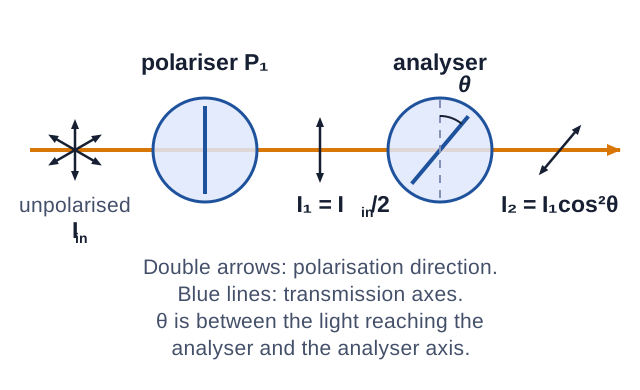
Only the field component along the analyser axis passes: an amplitude E₀ becomes E₀ cos θ. Intensity is proportional to amplitude squared, so
I = I₀ cos² θ.
Apply the law one element at a time. After each polariser the light is polarised along that polariser’s axis, and its intensity becomes the I₀ for the next element.
Worked chain. Randomly polarised light of intensity 80 W m⁻² passes through three ideal polarisers with transmission axes at 0°, 30° and 90° to the vertical.
- First polariser: I₁ = 80/2 = 40 W m⁻², polarised at 0°.
- Second: the angle between the arriving polarisation (0°) and the axis (30°) is 30°, so I₂ = 40 cos² 30° = 30 W m⁻², now polarised at 30°.
- Third: the angle is 90° - 30° = 60°, so I₃ = 30 cos² 60° = 7.5 W m⁻².
Without the middle polariser, the first and last are crossed and transmit nothing. Inserting a polariser between them increases the output because it changes the polarisation reaching the last one.
Using the original intensity, or the angle from the first polariser, at every step. For the third polariser above, 80 cos² 90° or 40 cos² 90° both give zero, which contradicts the 7.5 W m⁻² actually transmitted.
Try it first. Randomly polarised light of intensity 120 W m⁻² passes through ideal polarisers with axes at 0°, 45° and 90°. Find the intensity after each one, then the output if the 45° polariser is removed.
Check your chain
After the first: 60 W m⁻². After the second: 60 cos² 45° = 30 W m⁻². After the third: 30 cos² 45° = 15 W m⁻², because the light reaching it is polarised at 45°. Removing the middle polariser leaves two crossed polarisers, so the output is zero. If you obtained 0 with the middle polariser in place, you measured the last angle from the first polariser instead of from the light that reaches it.
3. Polarisation by reflection: the Brewster angle
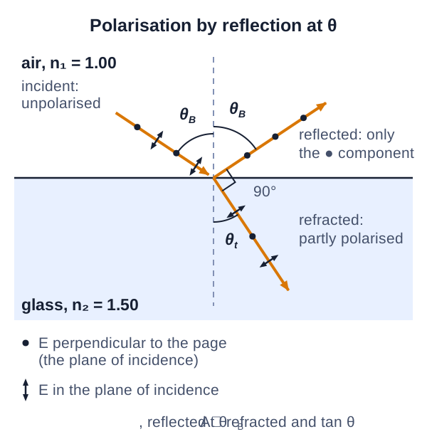
Resolve the incident field into a component perpendicular to the plane of incidence (dots in the figure) and a component in the plane of incidence (double arrows). For light travelling in medium 1 (index n₁) towards medium 2 (index n₂), there is one angle of incidence at which the in-plane component is not reflected at all. This is the Brewster angle, θ_B.
At θ_B the reflected and refracted rays are perpendicular, so θ_B + θₜ = 90°. Snell’s law then gives
tan θ_B = n₂/n₁.
Derivation from Snell's law
Snell’s law: n₁ sin θ_B = n₂ sin θₜ. With θₜ = 90° - θ_B, sin θₜ = cos θ_B, so n₁ sin θ_B = n₂ cos θ_B and tan θ_B = n₂/n₁.
Why the in-plane component vanishes. The refracted wave drives electrons in medium 2 to oscillate along its field. For the in-plane component, that oscillation lies in the plane of incidence, perpendicular to the refracted ray. When the reflected and refracted rays are perpendicular, this oscillation direction points along the reflected ray. An oscillating dipole radiates nothing along its own axis, so the reflected wave receives no in-plane component. The perpendicular component drives oscillations normal to the page, which do radiate along the reflected direction.
Consequences:
- The reflected light at θ_B is linearly polarised perpendicular to the plane of incidence. For reflection from a horizontal surface, that is horizontal. Polarising sunglasses with vertical transmission axes block this glare.
- The refracted light still carries both components, so it is only partly polarised.
- θ_B depends on which medium the light starts in. Air to glass (n = 1.50): θ_B = tan⁻¹ 1.50 = 56.3°. Glass to air: θ_B = tan⁻¹ (1/1.50) = 33.7°.
- θ_B is an angle of incidence measured from the normal. Do not confuse it with the analyser angle θ in Malus’s law, which is measured between a polarisation direction and a transmission axis.
Try it first. Light travelling in water (n = 1.33) reflects from a glass block (n = 1.50). Find the Brewster angle and the angle of the refracted ray, and state the polarisation of the reflected light.
Check your Brewster reasoning
θ_B = tan⁻¹ (1.50/1.33) = 48.4°. The refracted ray is at 90° - 48.4° = 41.6° to the normal; check: 1.33 sin 48.4° ≈ 1.50 sin 41.6° ≈ 0.995. The reflected light is linearly polarised perpendicular to the plane of incidence. Using tan⁻¹ 1.50 ignores that the light starts in water, not air.
4. Birefringence
In an optically anisotropic crystal such as calcite, the refractive index depends on the direction of the light’s electric field relative to a special direction in the crystal, the optic axis. A ray entering such a crystal generally splits into two rays with perpendicular polarisations:
- the ordinary ray (o-ray), whose field is perpendicular to the plane containing the optic axis and the ray. It has the same index nₒ in every direction and obeys Snell’s law;
- the extraordinary ray (e-ray), whose field has a component in that plane. Its index varies with propagation direction, between nₒ and a limiting value nₑ.
Which ray is which depends on the crystal’s optic-axis orientation relative to the ray, not on a fixed propagation direction. Light travelling exactly along the optic axis does not split, because its field is then perpendicular to the axis whatever its polarisation. For calcite at 589 nm, nₒ = 1.658 and nₑ = 1.486. The birefringence is Δ n = |nₑ - nₒ| = 0.172.
Because the two polarisations travel at different speeds, a plate of thickness d introduces a phase difference δ = 2π Δ n d/λ between them. This changes the polarisation state of the light that emerges.
Using birefringence between crossed polarisers
Crossed polarisers normally transmit no light. A birefringent sample placed between them changes the polarisation, so some light gets through.
- Photoelasticity: glass and many plastics become birefringent under mechanical stress. A plastic model of a component viewed between crossed polarisers shows coloured fringes that map the stress distribution.
- Liquid-crystal displays (LCDs): liquid-crystal molecules are themselves birefringent, and their orientation can be controlled. In a twisted-nematic cell between crossed polarisers, the molecules twist through 90° across the cell and guide the polarisation round, so light passes. An applied voltage turns the molecules to line up with the field, removing the twist, so the second polariser blocks the light. The display works by electrically reorienting birefringent molecules. It is not an example of the Kerr effect, which is birefringence induced in an otherwise isotropic material by an electric field.
Learn next
Continue with the next resource in this course.
Course and syllabus information
- Course
- Advanced Physics
- Edition
- Advanced Physics