Circuit diagrams, symbols and meters
Key idea: Circuit diagrams show connections with standard symbols. An ammeter goes in series to measure a component's current; a voltmeter goes across it to measure potential difference.
Offline pages
Saved on this device only. Connect at least once every 30 days to confirm Premium. Sign-out or a change of account removes saved copies.
Loading guide controls…
Guided lessons · coming soon
Guided lesson
Guided steps
- Compare the source, lamp, meter and resistor symbols.
- Sketch both symbols and explain their differences.
- Trace component endpoints, joined wires and crossing wires.
- Trace each complete path through the switches.
- Place the second switch where it breaks only L1’s path.
- Compare the paths needed to measure current and potential difference.
- Explain what this ammeter reads and correct its position.
- Explain how a series voltmeter affects current.
- Draw the main loop, then the voltmeter across the lamp.
- Draw both lamp branches and check each switch’s action.
- Find and correct all three symbol and meter errors.
On this page
You stopped at:
ContinueA circuit diagram is a map of a circuit: it shows what is connected to what, using standard symbols that anyone can read. Drawing one correctly matters most for meters, because an ammeter or a voltmeter in the wrong place measures the wrong thing or stops the circuit working. The meters measure current and potential difference (p.d.) from E.m.f., potential difference and resistance.
The symbols you need
A circuit diagram shows how the parts of a circuit are connected, not what they look like. Everyone uses the same symbols, so anyone can read the diagram.
| Component | What it does | How the symbol is drawn |
|---|---|---|
| Cell | A source of e.m.f. | A long line and a short line. The long line is the positive terminal. |
| Battery | Two or more cells joined together | Two or more cell symbols joined end to end, long line to short line. |
| Switch | Opens or closes a gap in the circuit | A break in the wire with a hinged line. An open switch stops the current. |
| Lamp | Lights up when there is a current in it | A circle with a cross inside. |
| Light-emitting diode (LED) | Gives out light when there is a current in it | A triangle pointing in the direction of the conventional current it lets through, a bar at its tip, and two small arrows pointing away for the light. |
| Fixed resistor | Has a resistance that does not change | A plain rectangle. |
| Variable resistor | Has a resistance you can change, to change the current | A rectangle with an arrow drawn diagonally through it. |
| Fuse | Melts and breaks the circuit if the current is too large | A small rectangle with the wire running straight through it. |
| Ammeter | Measures current | A circle with the letter A. |
| Voltmeter | Measures potential difference | A circle with the letter V. |
Three pairs are easy to mix up:
- Cell and battery. A cell has one pair of lines. A battery has two or more pairs.
- Lamp and meter. Both are circles. A lamp has a cross; a meter has a letter.
- Fixed and variable resistor. Only the variable resistor has the arrow through it.
Check your understanding 1
Cover the table and sketch both symbols on paper. Describe the symbol for a variable resistor and the symbol for a fuse, and say how they differ from a fixed resistor.
Show answer
A variable resistor is a rectangle with a diagonal arrow through it. A fuse is a smaller rectangle with the wire drawn straight through its middle. A fixed resistor is a plain rectangle, with no arrow and no line through it.
Drawing a circuit diagram
Follow these rules every time:
- Draw every wire as a straight line with a ruler. Corners are right angles.
- Put each symbol on a wire, with no gaps between the symbol and the wire.
- Make sure there is a complete loop from one terminal of the source, through the components, back to the other terminal. Without a complete loop there is no current.
- Draw a dot wherever wires are joined.
The lines are ideal wires: they have no resistance. Bending, stretching or moving a wire on the page does not change the circuit, as long as every component stays connected to the same points.
Joined wires and crossing wires
A dot means the wires are joined, so charge can pass from one to the other. Two lines that cross without a dot are not joined: one wire passes over the other.
To check whether two diagrams show the same circuit, trace each component’s two ends. If every component connects to the same points in both diagrams, they are the same circuit, even if one is drawn as a tall rectangle and the other as a wide one.
What a switch controls
A switch can only break the path it is in. Where you draw it decides what it controls.
On the left, every path from the cell passes through S, so opening S turns off both lamps. On the right, S is in the branch with L2 only. Opening S turns off L2, but L1 still has a complete path through its own branch, so it stays lit.
Check your understanding 2
In the right-hand circuit, where would you add a second switch so that it turns off L1 only?
Show answer
In the branch with L1, between the two junctions. It then breaks only L1’s path.
Connecting ammeters and voltmeters
Decide what you want to measure first.
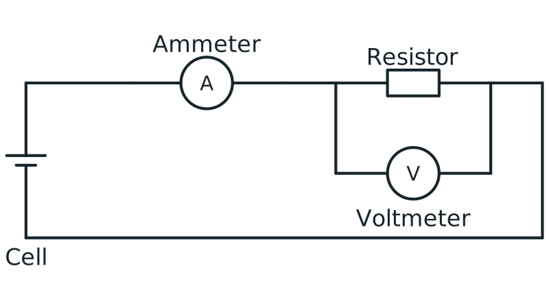
- Current is the rate of flow of charge through a component. The charge must pass through the ammeter, so connect the ammeter in series, in the component’s branch rather than in a main wire carrying several load-branch currents.
- Potential difference compares two points: one end of a component and the other. Connect the voltmeter in parallel, with one lead at each end of the component.
Voltmeter connection in parallel
Circuit with ammeter in series and voltmeter connected in parallel across a resistor to measure potential difference.
Scroll across the figure to read all labels.
View figure data
| Part | Connection |
|---|---|
| Ammeter | In series in the main loop |
| Voltmeter | In parallel across the resistor |
| Resistor | In the conducting loop with the cell and ammeter |
An ammeter has a very small resistance, so adding it in series hardly changes the current. A voltmeter has a very large resistance, so almost no current passes through it and it hardly changes the circuit. In ideal-meter calculations, take ammeter resistance as zero and voltmeter current as zero; a voltmeter connection then does not divert current from the component being measured.
Never connect an ammeter directly across a source: its very small resistance can let a dangerously large current flow.
Check your understanding 3
A resistor and a lamp are connected in parallel to a cell. A student places an ammeter in the wire between the cell and the first junction, and says it reads the current in the resistor. Is the student right? Where should the ammeter go?
Show answer
No. Before the junction, the ammeter carries the charge for both branches, so it reads the total current. To read the resistor’s current, place the ammeter in series in the resistor’s own branch, between the junctions, rather than carrying the combined current for both loads.
Check your understanding 4
A learner connects a voltmeter in series with a lamp and a cell. Explain why the lamp does not light.
Show answer
The voltmeter has a very large resistance. In series it is part of the only path, so almost no current flows round the circuit and the lamp does not light.
Draw a circuit from a description
Task. Draw a circuit in which a battery, a switch, a lamp and a variable resistor are connected in series. An ammeter measures the current in the lamp, and a voltmeter measures the p.d. across the lamp.
- Find the main loop. The battery, switch, lamp and variable resistor are in series, so they go in one loop. The ammeter must be in series with the lamp, so it goes in the same loop. Draw that loop first, one symbol after another.
- Add the voltmeter last. It measures the p.d. across the lamp only, so connect one lead to the wire just before the lamp and the other just after it. Mark both connections with dots.
- Check the drawing. There is one complete loop. The ammeter reads the lamp branch’s current; the ideal voltmeter draws no current. The voltmeter’s leads meet the loop on either side of the lamp and nowhere else, so it is not across the variable resistor as well.
The order of the series components round the loop does not matter: charge passes through each of them in turn wherever they are drawn.
Check your understanding 5
Draw on paper a circuit in which a battery and a fuse are connected to two lamps in parallel. One switch must turn both lamps on and off together, and a second switch must turn off one lamp only.
Show answer
Self-review the drawing: the battery, fuse and first switch are in an unbranched main wire, before the split or after the branches rejoin, so every lamp path includes them. Each lamp is in its own branch between the same two junctions, with dots at both junctions. The second switch is in one lamp’s branch only.
Find the errors
Check your understanding 6
Compare the diagram with the task in its caption. Find three errors, and say how to correct each one.
Show answer
- The resistor has an arrow through it. That is the symbol for a variable resistor. Draw a plain rectangle for a fixed resistor.
- The voltmeter is in series in the top wire. It should measure the p.d. across the resistor, so remove it from the loop, close the gap with wire, and connect it in parallel, with one lead at each end of the resistor.
- The ammeter is in parallel with the lamp. Most of the current would take the ammeter’s low-resistance path instead of passing through the lamp. Remove it from its separate wire and place it in the loop in series with the lamp.
Common mistakes
- Connecting an ammeter across a component. Its small resistance lets a large current bypass the component; put the ammeter in series, in the component’s path.
- Connecting a voltmeter in series. Its very large resistance lets almost no current through; connect it in parallel, across the component.
- Leaving a gap between a symbol and a wire. The loop is broken, so there is no current.
- Treating wires that cross without a dot as joined. Draw a dot only where wires really join.
- Drawing a plain circle for a lamp or meter. A lamp has a cross, an ammeter an A and a voltmeter a V.
- Connecting a voltmeter across two components. Its leads go at the two ends of the one component you want.
Spotted an error? Report a correction
Syllabus and review details
- SEC G2 Science Physics component 2027 · 2027
Physics section, PDF pages 8–23
Last reviewed: