D.C. Circuits
Key idea: Circuit symbols, meter placement, series and parallel rules, effective resistance and whole-circuit calculations.
Continue where you stopped
The core idea
On this page
Learning objectives
- Recognise and interpret circuit symbols for cells, batteries, switches, lamps, LEDs, resistors, fuses, ammeters and voltmeters
- Draw circuit diagrams with cells, batteries, switches, lamps, LEDs, fixed and variable resistors, fuses, ammeters and voltmeters
- Apply the same-current rule in series circuits
- Apply the potential-difference sum in series circuits
- Apply current conservation at parallel junctions
- Apply equal potential difference across parallel branches
- Calculate effective resistance in series
- Calculate effective resistance in parallel
- Solve whole-circuit problems using consistent quantities
Syllabus and review details
For this Science course, focus on the required circuit symbols, series and parallel rules, effective resistance and whole-circuit calculations. Potential dividers and sensor circuits are not required.
- K223 / K224 Science Physics componentK223 / K224 · 2027Checked against the syllabus · complete topic coverageK223/K224 2027 syllabus, D.C. Circuits topic 11
Begin with connections: which terminals share a conducting path? Then use charge conservation for currents and energy per charge for potential differences. Choose a resistance rule only after tracing those connections.
Draw standard symbols and connect meters correctly
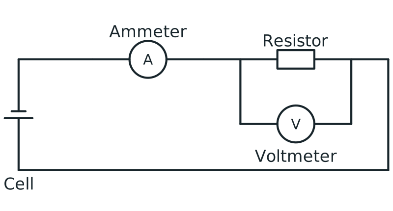
Voltmeter connection in parallel
Circuit with ammeter in series and voltmeter connected in parallel across a resistor to measure potential difference.
View figure data
| Part | Connection |
|---|---|
| Ammeter | In series in the main loop |
| Voltmeter | In parallel across the resistor |
| Resistor | In the conducting loop with the cell and ammeter |
Be able to draw a cell or battery, switch, lamp, LED, fixed resistor, variable resistor, fuse, ammeter and voltmeter. Use straight connecting lines and a junction dot only where wires are electrically joined.
Follow nodes, not the shape on the page
A node is a set of points joined by an uninterrupted ideal wire. Bending or stretching that wire does not change the connections. Crossing lines are not enough to establish a connection: read the junction dot or bridge convention. A switch gap breaks the conducting path, while a resistor connects two different nodes.
To place a meter, identify the quantity first. Current describes charge passing through a path; potential difference compares two points. Trace each meter terminal back to the circuit before deciding whether its placement measures the intended quantity.
Ammeter
Connect in series so the branch current passes through it.
Voltmeter
Connect in parallel across the component or two points being compared.
In the meter figures, which connection makes the lamp or resistor's current pass through the ammeter?
The ammeter is inserted in the same unbranched path as the component. A voltmeter instead has one terminal at each end of the component, so it compares those two nodes.
In series, current is the same and potential differences add
There is one path, so the current is the same at every point:Isource = I1 = I2. Energy conservation givesVsource = V1 + V2 + ….
In the left-hand diagram, trace the single loop through both resistors. Charge cannot steadily enter the first resistor faster than it leaves the second without accumulating somewhere. The current is therefore common. Each coulomb transfers energy in both resistors, so their energy-per-charge values add to the source value.
Unequal resistances need not share the p.d. equally
Let the two series resistors be 2 Ω and 4 Ω across 12 V. Their total is 6 Ω, giving 2 A throughout. Their p.d.s are 2 × 2 = 4 V and 2 × 4 = 8 V. Check the whole loop: 4 + 8 = 12 V. Equal current does not mean equal p.d.
Opening a switch is different from adding resistance
An open switch breaks the only loop, so there is no steady current anywhere in it. Adding a finite resistance keeps a closed path but increases total resistance, reducing the current for the same ideal supply. Zero current does not require every p.d. to be zero: the open switch can have the supply p.d. across its gap.
A learner says the second series resistor receives less current because the first uses some up. What must change in the explanation?
Replace charge consumption with energy transfer. The same charge per second passes through both resistors; each transfers some energy from that charge.
In parallel, potential difference is equal and branch currents add
Each branch connects across the same two points, soVsource = V1 = V2. Charge conservation at a junction givesIsource = I1 + I2 + ….
Return to the right-hand diagram above. Trace the upper wire rail as one node and the lower rail as another. Both resistors have one end on each rail, so each spans the same two electrical potentials. The result depends on their endpoints, not on whether the resistor symbols look parallel on the page.
Split the charge flow and recombine it
With a 12 V ideal supply, branches of 6 Ω and 3 Ω carry 2 A and 4 A. The supply carries 6 A before the split and after the branches rejoin. Check that 2 + 4 = 6 A; do not divide the 12 V between the branches.
If only the 6 Ω branch is disconnected, what happens to the 3 Ω branch and the supply current?
The 3 Ω branch still spans the same ideal 12 V supply, so it still carries 4 A. The disconnected branch carries no current; supply current falls to 4 A. This differs from opening the single path of a series loop.
Effective resistance: replace a group without changing its terminal behaviour
The equivalent resistance must draw the same total current for the same p.d. across the group's two terminals. First identify those terminals and trace the branches between them. A formula cannot repair a mistaken connection map.
Add series resistances directly
Rtotal = R1 + R2 + …
For 4 Ω and 8 Ω in series, Rtotal = 12 Ω.
Add reciprocal resistances in parallel
1 / Rtotal = 1 / R1 + 1 / R2 + …
For 6 Ω and 3 Ω in parallel, 1/R = 1/6 + 1/3 = 1/2, soRtotal = 2 Ω. The answer is below the smallest branch resistance, as it must be.
The additional conducting path lets more total charge pass each second at the same p.d. Therefore V/I for the whole pair is smaller than for either branch alone. If your answer exceeds the smallest positive branch resistance, check the connection map and whether you took the final reciprocal.
Reduce the network before applying R = V / I
Start at B and follow both paths to C: each contains a 6 Ω resistor. Those resistors share both endpoints, so their equivalent resistance between B and C is 3 Ω. The 4 Ω resistor connects A to B; it is not a third branch between B and C, even though R₀ and R₁ lie on the same horizontal line.
After replacing the B–C pair, the source drives 4 Ω + 3 Ω = 7 Ω. The source current is I = V/R = 14/7 = 2.0 A. R₀ has a p.d. of 2 × 4 = 8 V, leaving 14 − 8 = 6 V between B and C. Each 6 Ω branch therefore carries 1 A; 1 + 1 = 2 A checks the junction.
A learner adds 4 + 6 + 6 = 16 Ω because the wires form one connected drawing. Is the first error topology or arithmetic?
The addition is correct, but the connection model is wrong. Current has two paths from B to C, so the two 6 Ω resistors do not carry the whole source current. Reduce that parallel pair before adding R₀.
- Identify series and parallel groups.
- Calculate effective resistance from the innermost group outward.
- Use a p.d., current and resistance that describe the same part of the circuit.
- Apply current and p.d. rules to recover branch values.
Common mistakes
“Current is used up in series.”
Remember: current is the same; component p.d.s add.
“The supply p.d. is divided equally between parallel branches.”
Remember: every branch connected across the same two nodes has the full branch-to-branch p.d.; it is current that divides among branches.
“Parallel resistances add directly.”
Remember: add reciprocals and take the final reciprocal.
“Use supply V with any resistor.”
Remember: V, I and R must refer to the same circuit section.
Challenge yourself
Two identical 12 Ω resistors are connected first in series and then in parallel across the same 12 V supply. Compare the current through each resistor, the p.d. across each resistor and the total current from the supply.
Check your thinking
In series, total resistance is 24 Ω, so the current is 12/24 = 0.50 A everywhere. Each identical resistor has 6.0 V across it. In parallel, each resistor has the full 12 V across it, so each branch current is 12/12 = 1.0 A. The supply current is 1.0 + 1.0 = 2.0 A.
Check your understanding
Worked example: solve a mixed circuit from the inside out
Trace B to C again. The endpoints are unchanged, but the branch resistances now differ. R₀ is 4 Ω, R₁ is 6 Ω and R₂ is 3 Ω, with an 18 V ideal source.
- The parallel pair has resistance 2 Ω because 1/R = 1/6 + 1/3 = 1/2.
- Total resistance = 4 + 2 = 6 Ω.
- Supply current = 18/6 = 3.0 A. This current passes through the 4 Ω series resistor.
- P.d. across the 4 Ω resistor = 3.0 × 4 = 12 V.
- The parallel pair therefore has 18 − 12 = 6.0 V across it.
- Branch currents are 6.0/6 = 1.0 A and 6.0/3 = 2.0 A; they add to the 3.0 A supply current.
Guided practice
1.2 A enters a junction; 0.45 A leaves one branch. Find the other current.
1.2 − 0.45 = 0.75 A.
Find the effective resistance of 4 Ω and 12 Ω in parallel.
1/R = 1/4 + 1/12 = 1/3, so R = 3 Ω.
Why is a parallel result below either branch resistance?
Adding another path allows more total current for the same p.d., so V/I is smaller.
Practise this independently
- Draw a circuit containing a battery, a switch that controls the whole circuit, two resistors in parallel, an ammeter measuring the supply current and a voltmeter measuring the p.d. across one resistor.
- Two resistors, 2.0 Ω and 4.0 Ω, are connected in series across 12 V. Find the effective resistance, circuit current and p.d. across each resistor.
- Two resistors, 6.0 Ω and 3.0 Ω, are connected in parallel across 12 V. Find the effective resistance, each branch current and the supply current.
- A 5.0 Ω resistor is in series with a parallel pair of 10 Ω and 15 Ω resistors across a 22 V supply. Find the effective resistance, supply current, p.d. across each part and both branch currents.
Check your answers
- The switch and ammeter must be in the single supply path before or after the junction. The two resistors form separate branches between the same two junctions. The voltmeter is connected in parallel across either resistor. Use standard symbols and junction dots where wires join.
- Rtotal = 2.0 + 4.0 = 6.0 Ω; I = 12/6.0 = 2.0 A. The p.d.s are 2.0 × 2.0 = 4.0 V and 2.0 × 4.0 = 8.0 V, which add to 12 V.
- 1/R = 1/6.0 + 1/3.0 = 1/2.0, so R = 2.0 Ω. Branch currents are 12/6.0 = 2.0 A and 12/3.0 = 4.0 A. Supply current = 2.0 + 4.0 = 6.0 A.
- The parallel pair is 6.0 Ω, so total resistance is 11 Ω and supply current is 2.0 A. The 5.0 Ω resistor has 10 V across it, leaving 12 V across each branch. Branch currents are 12/10 = 1.2 A and 12/15 = 0.80 A; they add to 2.0 A.
Try this next
Change one resistance in question 3 and solve it again. Before calculating, predict whether the supply current should rise or fall and check that your final answer agrees.
Practise this topic
The topic check covers circuit symbols and series rules, parallel circuits, and resistance in whole circuits. Use the feedback to return to the matching explanation before trying a fresh question.
Practise
Practise: D.C. Circuits
A text-first D.C. circuits assessment with circuit topology, nodes, branches, quantities and units stated explicitly.
About 10 minutes
Practise
Questions are selected when you start. Use the feedback to decide what to practise next; this does not prove mastery.
Recent attempts
History is stored only in this browser.
No completed attempts are saved yet.
Beyond the syllabus: optional enrichment that does not count towards your progress.
Practise
Practise after feedback: D.C. Circuits
A text-first D.C. circuits assessment with circuit topology, nodes, branches, quantities and units stated explicitly.
About 10 minutes
Practise
Questions are selected when you start. Use the feedback to decide what to practise next; this does not prove mastery.
Recent attempts
History is stored only in this browser.
No completed attempts are saved yet.
Beyond the syllabus: optional enrichment that does not count towards your progress.
Check what I know
Check what I know: D.C. Circuits
A text-first D.C. circuits assessment with circuit topology, nodes, branches, quantities and units stated explicitly.
About 8 minutes
Check what I know
Answer 6 short questions. This starting check helps choose what to work on; it does not prove mastery.
Recent attempts
History is stored only in this browser.
No completed attempts are saved yet.
Beyond the syllabus: optional enrichment that does not count towards your progress.
Check my progress
Check my progress: D.C. Circuits
A text-first D.C. circuits assessment with circuit topology, nodes, branches, quantities and units stated explicitly.
About 10 minutes
Check my progress
Answer 9 questions. If accepted, this result can contribute to your course progress.
Recent attempts
History is stored only in this browser.
No completed attempts are saved yet.
Beyond the syllabus: optional enrichment that does not count towards your progress.
Check again
Check again: D.C. Circuits
A text-first D.C. circuits assessment with circuit topology, nodes, branches, quantities and units stated explicitly.
About 10 minutes
Check again
Answer 9 questions. If accepted, this result can contribute to your course progress.
Recent attempts
History is stored only in this browser.
No completed attempts are saved yet.
Beyond the syllabus: optional enrichment that does not count towards your progress.
Review
Review: D.C. Circuits
A text-first D.C. circuits assessment with circuit topology, nodes, branches, quantities and units stated explicitly.
About 10 minutes
Review
Answer 9 questions. A scheduled review can contribute to your course progress only when it is due and the result is accepted.
Recent attempts
History is stored only in this browser.
No completed attempts are saved yet.
Beyond the syllabus: optional enrichment that does not count towards your progress.
Course and syllabus information
- Course
- SEC G2 Science Physics component
- Edition
- SEC G2 Science Physics component 2027