Wire length and resistance
Key idea: Vary the measured length of one wire and find each resistance from voltage divided by current. Keep the wire cool and its thickness unchanged to test resistance against length.
Offline pages
Saved on this device only. Connect at least once every 30 days to confirm Premium. Sign-out or a change of account removes saved copies.
Loading guide controls…
Guided lessons · coming soon
Guided lesson
Guided steps
- Match the wire length to both meter connections.
- Choose the measured section and correct the voltmeter connection.
- Calculate each resistance, then divide by its measured length.
- Find the ratio, gradient and intercept before testing direct proportion.
- Use each trial’s contact separation and paired current.
- Explain the resistance comparison and suggest further measurements.
On this page
You stopped at:
ContinueIn a longer wire, moving electrons encounter more resistance along their path. For the same material, thickness and temperature, resistance increases with length. Moving a crocodile clip along a single wire lets you change its length while keeping the material and thickness the same, and the circuit from resistance of a component measures each resistance. Use only the low-voltage supply provided, switch off before moving a clip, and keep the current small: the wire and contacts can become hot.
Resistance and the length of a wire
The paired-meter method now tests a new variable: the length of wire between two contacts. Connect the voltmeter across exactly that section, and keep the material, cross-sectional area and temperature approximately constant.
For a uniform wire at constant temperature, resistance is expected to be directly proportional to length. Review resistance and wire dimensions.
- Tape a constantan wire along a metre rule. Connect one end of it into the circuit in place of the component.
- Make the second connection with a crocodile clip or jockey at a length l along the wire. Measure l between the two contact points.
- Connect the voltmeter across that length only.
- With the circuit switched off, set the contacts and voltmeter leads for the selected length. Switch on briefly, adjust to a small suitable current, read V and I together, then switch off. Keep the on-time brief to limit heating.
- Repeat across a range of lengths, using the same wire. Recheck readings at a smaller current if resistance drifts, and record repeats so you can judge the scatter.
Check your understanding 1 The wrong section
Current passes through 0.60 m of wire, but the voltmeter spans only 0.40 m. Which section’s resistance does V/I give? How should the voltmeter be connected for the 0.60 m section?
Show answer
V/I gives the resistance of the 0.40 m section only. Switch off, then connect the voltmeter across the two contacts marking the 0.60 m length.
These constructed example readings use five lengths and the same nominal small current. The values are for practising analysis, not reported measurements.
| l / m | V / V | I / A |
|---|---|---|
| 0.200 | 0.25 | 0.30 |
| 0.400 | 0.55 | 0.30 |
| 0.600 | 0.80 | 0.30 |
| 0.800 | 1.05 | 0.30 |
| 1.000 | 1.30 | 0.30 |
Resistance against selected wire length
Five wire lengths from 0.200 m to 1.000 m have calculated resistances from about 0.83 Ω to 4.33 Ω. The points lie close to a straight illustrative fit with gradient about 4.33 Ω/m and a small intercept of about 0.03 Ω. The table gives each plotted coordinate.
Scroll across the figure to read all labels.
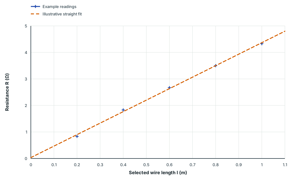
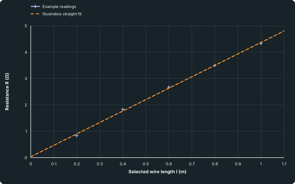
View figure data
| Series | Selected wire length l (m) | Resistance R (Ω) |
|---|---|---|
| Example readings | 0.2 | 0.83300 |
| Example readings | 0.4 | 1.83000 |
| Example readings | 0.6 | 2.67000 |
| Example readings | 0.8 | 3.50000 |
| Example readings | 1.0 | 4.33000 |
| Illustrative straight fit | 0.0 | 0.03333 |
| Illustrative straight fit | 1.1 | 4.80000 |
The example fit is drawn freely rather than forced through zero. Repeat the measurements and check the meters before explaining a small offset.
Guided practice 1
Is resistance proportional to length?
Problem
For the 0.600 m and 0.400 m rows, calculate resistance divided by length. Use V/I for each resistance. The full solution compares all five rows.
Try this before viewing the solution
Show the steps Optional working
Show the steps Optional working
Hints
Hint 1
one row at a time
Use R = V/I with the readings in the same row.
Hint 2
what stays the same?
If R is directly proportional to l, what is the same for every row?
Show solution step by step
Resistance of each length
Method
Divide each V by the current in the same row.Reason
V and I were read together for that length.Working
Answer
R = 0.83 Ω, 1.83 Ω, 2.67 Ω, 3.50 Ω and 4.33 Ω.
Test for proportionality
Method
Work out R/l for each row.Reason
Direct proportion means R/l is the same for every length: a graph of R against l is a straight line through the origin.
Working
Answer
R/l = 4.17, 4.58, 4.44, 4.38 and 4.33 Ω/m. The ratios are close to about 4.4 Ω/m.
Assess the deviations
Method
State the conclusion and which readings are most affected by a given voltage-reading error.
Reason
The shortest lengths have the smallest potential differences. A given absolute voltage-reading error has a larger fractional effect there; repeated readings and the meter specifications are needed to assess uncertainty.
Working
Answer
“The results are approximately consistent with resistance increasing in direct proportion to length over the tested range. The R-against-l pattern is nearly straight and close to the origin, with a gradient around 4.3–4.4 Ω/m. Repeat readings to check the scatter around the trend.”
State the conclusion
Working
Answer
The results are approximately consistent with R being proportional to l over the tested range. Repeats and meter specifications are needed to judge whether the departures are within measurement uncertainty.
Quick check
Keep the current small and switch on briefly. If repeat readings drift, try a smaller current to check for heating.
Check your understanding 2 A line that misses the origin
A straight resistance–length graph gives 4.0 Ω at 0.50 m and 6.0 Ω at 1.00 m. Find the resistance ratio R(1.00 m)/R(0.50 m), the gradient and the intercept. Is resistance directly proportional to length?
Show the steps Optional working
Show the steps Optional working
Show answer
The resistance ratio is 6.0/4.0 = 1.5, while length doubles. Gradient = (6.0 − 4.0)/(1.00 − 0.50) = 4.0 Ω/m. Intercept = 4.0 − 4.0 × 0.50 = 2.0 Ω. A non-zero intercept means this straight line is not direct proportion.
Check your understanding 3 Use each trial’s own current
Contacts in trial A lie at 0.10 m and 0.40 m: V = 0.60 V, I = 0.20 A. In B they lie at 0.20 m and 0.80 m: V = 0.90 V, I = 0.15 A. Find each selected length and resistance.
Show answer
A: length = 0.40 − 0.10 = 0.30 m, resistance = 0.60/0.20 = 3.0 Ω. B: length = 0.80 − 0.20 = 0.60 m, resistance = 0.90/0.15 = 6.0 Ω.
Check your understanding 4 Explain the comparison
The same uniform wire was kept at the same temperature in both trials. Explain what the results suggest about resistance and length, despite the different currents. What further readings would strengthen the conclusion?
Show answer
Doubling length from 0.30 m to 0.60 m doubles resistance from 3.0 Ω to 6.0 Ω; R/length is 10 Ω/m in both trials. Different paired currents are suitable for comparison while material, thickness and temperature stay fixed. Test more lengths with repeats, then inspect a freely fitted resistance–length graph.
Common mistakes
- Measuring the length from the end of the rule instead of between the two contacts.
- Connecting the voltmeter across a different section from the one carrying the measured current.
- Leaving the current on so long that the wire warms up and its resistance rises.
- Forcing the best-fit line through the origin, or calling a line with a clear intercept direct proportion.
Spotted an error? Report a correction
Syllabus and review details
- SEC G2 Science Physics component 2027 · 2027
Physics section, PDF pages 8–23
Last reviewed: