Resistance of a component
Key idea: Measure voltage across a component and current through it together, then divide voltage by current to find resistance. Repeat at several settings and switch off between readings to limit heating.
Offline pages
Saved on this device only. Connect at least once every 30 days to confirm Premium. Sign-out or a change of account removes saved copies.
Loading guide controls…
Guided lessons · coming soon
Guided lesson
Guided steps
- Measure the component’s potential difference and current together.
- Choose each meter’s connection from what it measures.
- Check the axes and connect the gradient to resistance.
- Find resistance from two points on the specified line.
- Compare keeping a current setting with keeping temperature constant.
- Find both resistances and identify the effect of cooling.
- Compare reading errors and choose a suitable meter range.
- Find resistance and choose the correct voltmeter branch.
- Draw the corrected circuit and compare both meter connections.
On this page
You stopped at:
ContinueNo meter reads resistance directly in this investigation. Instead you measure the potential difference across a component and the current through it, at several settings, and find R = V/I from a graph of the readings. The method uses the meter connections from D.C. circuits, and its main problem is that the current warms the component and changes the very resistance you are measuring. Use only the low-voltage supply provided, have the circuit checked before switching on, and switch off before changing any connection.
Set up the circuit
V must be the potential difference across the component and I the current through it, measured at the same time.
Assume the voltmeter draws negligible current, so the ammeter reads the component current.
- Connect the cells, a switch, a rheostat, the ammeter and the component in one series loop.
- Connect the voltmeter across the component only, in parallel with it.
- Check that both analogue meters read zero before switching on. Use a range that safely covers the expected value; choose a more sensitive suitable range when needed, following the meter instructions.
- Switch on, set the rheostat, and read V and I together. Switch off.
- Take several paired readings within the component and meter ratings. Begin with a small current, switch off between readings and allow cooling if readings drift. A wide range is useful only while the component temperature stays approximately constant.
Check your understanding 1 Which meter must carry the component current?
Show answer
Connect the ammeter in series so it carries the component’s current. Connect the voltmeter in parallel across the component only. Wire with the supply switched off; an ammeter directly across a supply would make an unsafe low-resistance path.
These are constructed example readings for a resistor, read with an ammeter of full-scale deflection 1 A (to 0.01 A) and a voltmeter of full-scale deflection 3 V (to 0.05 V).
| V / V | I / A | R = V/I / Ω |
|---|---|---|
| 0.60 | 0.12 | 5.0 |
| 1.00 | 0.20 | 5.0 |
| 1.40 | 0.29 | 4.8 |
| 1.80 | 0.36 | 5.0 |
| 2.20 | 0.44 | 5.0 |
| 2.60 | 0.52 | 5.0 |
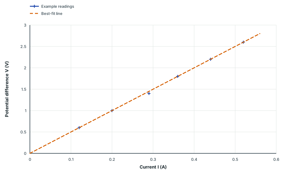
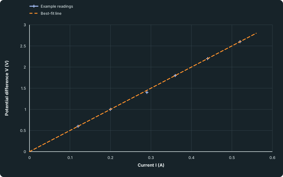
Potential difference against current for a resistor
Plotted points of potential difference V in V against current I in A for currents from 0.12 A to 0.52 A, with a dashed best-fit straight line through the origin. The data table lists every plotted value.
Scroll across the figure to read all labels.
View figure data
| Series | Current I (A) | Potential difference V (V) |
|---|---|---|
| Example readings | 0.12 | 0.6 |
| Example readings | 0.20 | 1.0 |
| Example readings | 0.29 | 1.4 |
| Example readings | 0.36 | 1.8 |
| Example readings | 0.44 | 2.2 |
| Example readings | 0.52 | 2.6 |
| Best-fit line | 0.00 | 0.0 |
| Best-fit line | 0.56 | 2.8 |
Worked example 1
Resistance from the graph
Problem
Use the graph of V against I to find the resistance of the resistor.
Show full solution
Check the shape
Method
The points lie close to a straight line through the origin.
Reason
A straight pattern through the origin is consistent with approximately constant V/I over this range, provided the temperature stays constant.
Working
Answer
At 1.40 V and 0.29 A, R = 4.83 Ω, about 3% below 5.0 Ω. It is close to the pattern, so check repeated readings before deciding its cause.
Find the gradient
Method
Read (0.10 A, 0.50 V) and (0.50 A, 2.50 V) from the line.Reason
For a straight V-against-I line through the origin, V = RI, so the gradient Δ V/Δ I equals the constant resistance.Working
Answer
R = (2.50 - 0.50)/(0.50 - 0.10) = (2.00 V)/(0.40 A) = 5.0 ΩState the resistance
Working
Answer
The resistance is 5.0 Ω over the measured range, with temperature approximately constant.
Quick check
Check your understanding 2 Read another V-against-I gradient
Show the steps Optional working
Show answer
For this origin-passing constant-temperature line, R = ΔV/ΔI = (3.60 − 0.40)/(0.45 − 0.05) = 8.0 Ω. The axis order matters. An I-against-V gradient would be 1/R, not R.
Keep the component cool
A current warms the component it passes through, and the resistance of a typical metal wire generally rises as it warms up; the size of the change depends on the material. Leaving the current on can raise the temperature and change V/I. For a metal wire whose resistance rises with temperature, the ratio drifts upwards. Switch off between readings, allow cooling and keep currents small. Recheck an earlier setting to see whether the resistance is drifting.
Check your understanding 3 Readings that drift upwards
A metal wire initially carries 0.20 A at 1.0 V. After the current has been left on, it carries 0.16 A at the same p.d. After cooling, the current returns to 0.20 A. Calculate the resistance before and during the drift. Which observation supports heating rather than a permanent change to the wire?
Show answer
Initially, R = 1.0 ÷ 0.20 = 5.0 Ω. During the drift, R = 1.0 ÷ 0.16 = 6.25 Ω, about 6.3 Ω. Returning to the original current after cooling also returns the resistance to 5.0 Ω. That reversibility supports a temperature effect rather than a permanent change. Switch off between readings and allow cooling to keep the temperature approximately constant.
Evaluate the method
Worked example 2
Evaluating the resistor experiment
Problem
The smallest current in the resistor table is 0.12 A, read on a 1 A meter to 0.01 A. Evaluate this reading and suggest an improvement.
Show full solution
Source
Method
The reading uses only a small part of the scale.Reason
An absolute current-reading error has a larger fractional effect on a smaller current. A display or recording step is only one contribution to uncertainty.
Working
Answer
For illustration, 0.01 A is about 8% of 0.12 A, but about 2% of 0.52 A. They show why the same reading error matters more for a small reading.
Effect
Method
For a given absolute current-reading error, the fractional effect on R = V/I is largest at the smallest currents.
Reason
A small error in a small current makes a large change in V/I.
Working
Answer
A fit uses all the readings to judge the trend and can reduce the effect of random scatter. It cannot remove a common meter offset or a temperature change.
Choose a suitable range
Method
Use a meter range, or a milliammeter, on which small currents give a large deflection.
Reason
A suitable lower range may give a finer absolute reading step, making the reading error a smaller fraction of the measured current.
Working
Answer
Also look straight at the scale, so that there is no parallax, and check the needle reads zero before switching on.
Give the evaluation
Working
Answer
A small current reading has a large fractional sensitivity to a fixed reading error. Choose a safe lower meter range with finer divisions for small currents, read straight-on and check the zero.
Quick check
Choose the range from the expected current and the instrument specifications. Check the zero and read straight at the scale as well.
| Source | Effect | Improvement |
|---|---|---|
| Current left on between readings | The component warms up and its resistance changes, so later values of V/I drift | Switch off between readings and keep the current small. |
| Meter needle not at zero before switching on | Every reading is shifted by the same amount | Adjust the zero, or subtract the zero reading. |
| Voltmeter connected across the ammeter and component together | V includes the potential difference across the ammeter | Connect the voltmeter across the component only. |
| Loose or dirty crocodile-clip contacts | Readings flicker or change when a wire is moved | Clean and tighten the connections. |
Check your understanding 4 Identify what the voltage measurement includes
A component carries 0.40 A with 1.80 V across it. The series ammeter has 0.20 V across it. Assume negligible voltmeter current. A voltmeter spanning both reads 2.00 V. Find the component resistance and choose where to reconnect the voltmeter.
Show answer
The component resistance is 1.80/0.40 = 4.5 Ω. Using the combined 2.00 V gives 5.0 Ω, including the ammeter’s 0.20/0.40 = 0.50 Ω. Reconnect the voltmeter across the component only, with the supply switched off.
Check your understanding 5 Compare the corrected circuit
Draw the corrected circuit on paper with a supply, open switch, rheostat, ammeter, component and voltmeter. Compare its meter branches with the model.
Show answer
The supply, open switch, rheostat, ammeter and component form one series loop. The voltmeter spans the component’s own endpoints in parallel, excluding the ammeter and rheostat. Change connections with the supply off.
The same circuit is used to find how a wire’s resistance depends on its length in wire length and resistance.
Common mistakes
- Connecting the ammeter across the component, or directly across the supply, instead of in series.
- Connecting the voltmeter across the ammeter and the component together instead of the component only.
- Taking V and I at different settings, or after the component has warmed up.
- Leaving the current on between readings, so the resistance drifts upwards.
- Taking the gradient of an I against V graph as R. On those axes the gradient is 1/R.
Spotted an error? Report a correction
Syllabus and review details
- SEC G2 Science Physics component 2027 · 2027
Physics section, PDF pages 8–23
Last reviewed: