I/V Graph Of Filament Lamp
Key idea: Learn why a filament lamp is non-ohmic, how heating makes its I–V graph curve, and how to calculate resistance at a point on the graph (O Level).
Continue where you stopped
The core idea
On this page
Learning objectives
- State current as rate of charge flow measured in amperes
- Distinguish conventional current from electron flow
- Apply charge equals current multiplied by time
- Define source e.m.f. as work done per unit charge around a circuit
- Calculate total e.m.f. for sources in series
- Define component potential difference as work done per unit charge
- State resistance as potential difference divided by current
- Apply resistance equals potential difference divided by current
- Apply wire-resistance proportionalities for length and cross-sectional area
- Describe the effect of temperature on metallic resistance
- Sketch and interpret required current–voltage characteristics
1. Definition
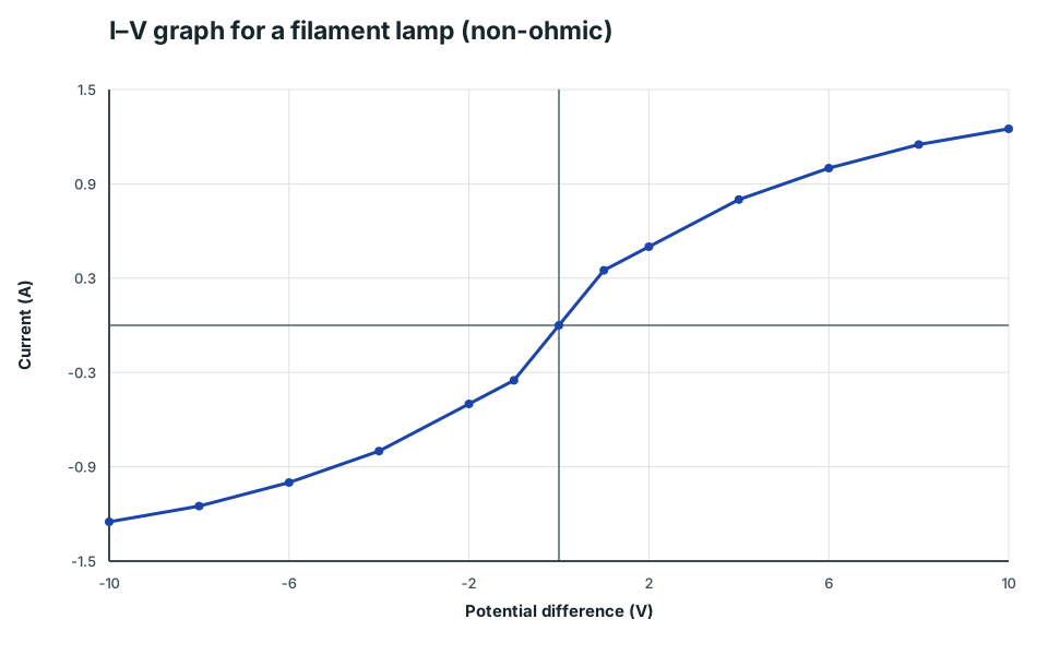
A filament lamp is non-ohmic: its resistance changes as current changes, so its I–V graph is a curve (not a straight line).
2. Key Ideas
- The filament heats up when current flows, so its resistance increases as it gets hotter.
- On an I vs V graph for a filament lamp:
- the curve becomes less steep as V increases (because R increases)
- R is not constant
- the complete curve has the same shape in the negative region because reversing p.d. reverses current
- Resistance at a point: R = V/I (use that point’s V and I).
You should be able to sketch and interpret the complete I–V characteristic of a filament lamp. Show the symmetric curve through the origin unless the axes restrict the range.
3. Detailed Explanations
A. Why the graph is curved
- Increase V across the lamp.
- Current I increases, so the filament heats up.
- Hotter filament → higher resistance.
- Higher resistance means current does not increase proportionally with voltage, so the graph curves.
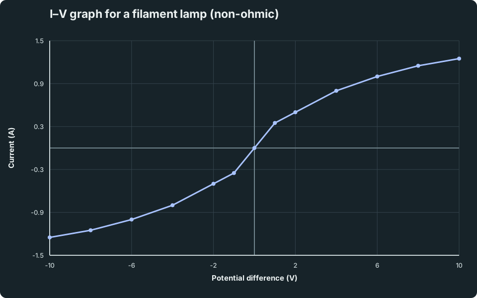
I–V graph for a filament lamp (non-ohmic)
A curved I–V graph that becomes less steep at higher voltages because the filament heats up and resistance increases.
Scroll across the graph to read all labels.
View figure data
| Potential difference (V) | Filament lamp |
|---|---|
| -10 | -1.25 |
| -8 | -1.15 |
| -6 | -1 |
| -4 | -0.8 |
| -2 | -0.5 |
| -1 | -0.35 |
| 0 | 0 |
| 1 | 0.35 |
| 2 | 0.5 |
| 4 | 0.8 |
| 6 | 1 |
| 8 | 1.15 |
| 10 | 1.25 |
B. How to compare resistance at different points
Pick two points on the curve and calculate R = V/I at each point. The point with the larger V/I has the larger resistance.
4. Common Mistakes
- Saying a filament lamp is ohmic (it is non-ohmic).
- Explaining the curve without mentioning heating and increasing resistance.
- Treating resistance as constant and using one R value for all points.
5. Exam Tips
- Sketch: a curve through the origin that becomes less steep as V increases.
- Explanation keywords: “current increases → filament heats → resistance increases”.
- If asked for resistance at a point: use R = V/I at that point.
6. Worked Examples
Modelled example 1
Resistance at a point
Problem
Study the worked solution
Use the point coordinates
Method
Divide the p.d. by the current at the same point.Reason
A non-ohmic device still has an operating-point resistance V/I.Working
R = 2.0/0.50 = 4.0 Ω
Guided practice 2
Comparing resistance at two points
Problem
Calculate both V/I ratios
Hints
Hint 1: do not compare voltage alone
Hint 2: connect to temperature
View solution step by step
Calculate and compare
Method
Find R_A = 4.0 Ω and R_B = 6.0 Ω.Reason
The hotter filament at B has greater lattice vibration and resistance.Working
R_A = 2.0/0.50 = 4.0 Ω; R_B = 6.0/1.0 = 6.0 Ω
Common misconception 3
Explaining the shape
Learner response
Track the direction of every change
View solution step by step
Build the heating chain
Method
State that greater voltage produces greater current and heats the filament.Reason
Higher temperature increases ion vibration and electron scattering.Working
V↑ ⇒ I↑ ⇒ T↑ ⇒ R↑.Explain the decreasing gradient
Method
State that current continues to rise, but less per additional volt.Reason
The increasing resistance reduces the I-against-V gradient.Working
Curve becomes less steep; current does not reverse.
Examiner practice 4
Another resistance calculation
Examination question
Calculate and qualify the result
View solution step by step
Calculate resistance
2 marksMethod
Use R = V/I at the stated coordinates.Reason
Both values describe the same operating point.Working
R = 4.0/0.80 = 5.0 ΩQualify the value
1 markMethod
State that resistance changes elsewhere on the curve.Reason
Filament temperature changes with current.Working
5.0 Ω applies at this point.
Self-mark with the mark scheme
Compare your response with each mark point. Select a point only when your response contains that evidence.
Self-mark equation, result and operating-point qualification.
Challenge 5
Is it ohmic?
Counterfactual transfer
Build the constant-resistance prediction first
Hints
Hint 1: make the ohmic prediction
Hint 2: explain the shortfall
View solution step by step
Predict the ohmic current
Method
Double 0.50 A to obtain 1.0 A.Reason
An ohmic conductor at constant temperature has I ∝ V.Working
2.0 → 4.0 V predicts 0.50 → 1.0 A.Interpret the actual current
Method
Use 0.80 A < 1.0 A to reject constant resistance.Reason
Heating raises filament resistance, so current grows less than proportionally.Working
Actual response is non-ohmic.
7. Mind Stretchers
Mind stretcher 1: Comparing with an ohmic conductorExtension
Two devices are tested. Device X gives a straight line through the origin on an I–V graph. Device Y gives a curved line that becomes less steep at higher voltages. Identify X and Y.
Show Answer
X is an ohmic conductor (metallic resistor at constant temperature). Y is a filament lamp (non-ohmic due to heating).
Mind stretcher 2: What happens if the filament stays cold?Extension
If the filament could be kept at constant temperature (no heating), what would happen to its I–V graph?
Show Answer
If temperature stays constant, resistance would be constant, so I ∝ V and the I–V graph would be a straight line through the origin (ohmic behaviour).
8. Practice and next step
Use the I–V Characteristics Lab to compare V/I near and far from the origin, then practise the heating explanation in Structured Current Electricity. Continue to the semiconductor diode.
Continue with the next resource in this course.
Course and syllabus information
- Course
- SEC G3 Physics
- Edition
- SEC G3 Physics 2027