LDR & Thermistor in Potential Dividers
Key idea: Learn how LDRs and NTC thermistors work in potential divider circuits, and practise O Level questions on how Vout changes with light and temperature.
Continue where you stopped
The core idea
On this page
Learning objectives
- Recognise and interpret circuit symbols for cells, batteries, switches, lamps, LEDs, resistors, fuses, ammeters and voltmeters
- Draw circuit diagrams with cells, batteries, switches, lamps, LEDs, fixed and variable resistors, fuses, ammeters and voltmeters
- Recognise and interpret circuit symbols for d.c. and a.c. supplies, potentiometers, bells, light-dependent resistors and thermistors
- Draw circuit diagrams with d.c. and a.c. supplies, potentiometers, bells, light-dependent resistors and thermistors
- Apply the same-current rule in series circuits
- Apply the potential-difference sum in series circuits
- Apply current conservation at parallel junctions
- Apply equal potential difference across parallel branches
- Calculate effective resistance in series
- Calculate effective resistance in parallel
- Solve whole-circuit problems using consistent quantities
- Describe variable-potential-divider action
- Describe NTC thermistor action as an input transducer
- Describe light-dependent resistor (LDR) action as an input transducer
- Solve simple NTC and LDR potential-divider problems
1. Definition
A. LDR
A light-dependent resistor (LDR) is a resistor whose resistance decreases when light intensity increases.
B. NTC thermistor
A negative temperature coefficient (NTC) thermistor is a resistor whose resistance decreases when temperature increases.
Using an LDR or NTC thermistor in a potential divider makes the output p.d. change with light or temperature, so it acts as an input transducer (physical change → voltage change).
You should be able to explain how LDRs and NTC thermistors act as input transducers in potential-divider circuits and solve simple circuit problems involving them.
2. Key Ideas
A. The divider relationship (output across the bottom resistor)
For a two-resistor divider (top R₁, bottom R₂), the output across R₂ is:
Vₒᵤₜ = Vₛ(R₂/(R₁ + R₂))
B. Sensor behaviour (must memorise)
- LDR: brighter → R smaller; darker → R larger
- NTC thermistor: hotter → R smaller; colder → R larger
C. Always state the arrangement
- which resistor is the sensor
- where Vₒᵤₜ is measured (across which part)
- use limiting cases (sensor resistance very large / very small) as a check
3. Detailed Explanations
A. A sensor in a potential divider
If a sensor is one of the resistors, changing its resistance changes the ratio, so Vₒᵤₜ changes.
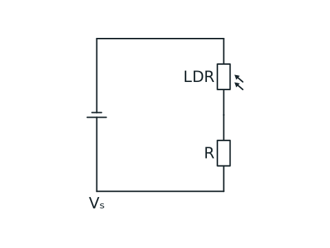
Potential divider with a sensor
An LDR sensor and fixed resistor are connected in series across a supply. The output potential difference is measured from their junction to the zero-volt end of the fixed resistor.
View figure data
| Part | Connection |
|---|---|
| LDR | Upper component in the divider |
| Fixed resistor R | Lower component; output is measured across it |
| NTC alternative | May replace the LDR in the same series position |
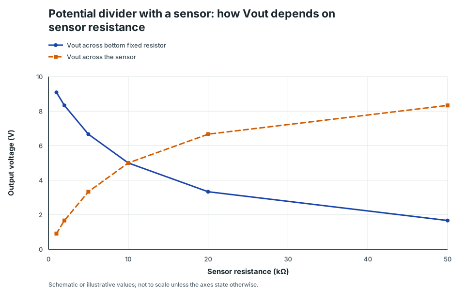
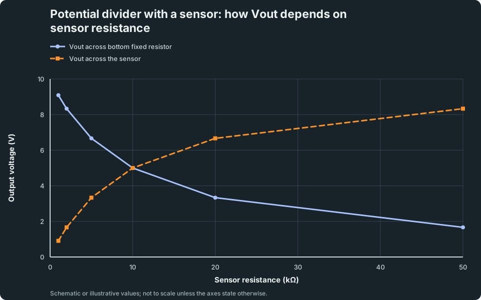
Potential divider with a sensor: how Vout depends on sensor resistance
With a sensor on top and a fixed resistor at the bottom, Vout can increase or decrease depending on which part you measure across.
Scroll across the graph to read all labels.
View figure data
| Sensor resistance (kΩ) | Vout across bottom fixed resistor | Vout across the sensor |
|---|---|---|
| 1 | 9.0909 | 0.9091 |
| 2 | 8.3333 | 1.6667 |
| 5 | 6.6667 | 3.3333 |
| 10 | 5 | 5 |
| 20 | 3.3333 | 6.6667 |
| 50 | 1.6667 | 8.3333 |
B. LDR example (light sensor)
Assume the LDR is on top and Vₒᵤₜ is taken across the bottom fixed resistor.
- brighter → R_LDR decreases → Vₒᵤₜ increases
- darker → R_LDR increases → Vₒᵤₜ decreases
If you measure Vₒᵤₜ across the LDR instead, the trend reverses.
C. NTC thermistor example (overheating alarm)
Assume the NTC thermistor is on top and Vₒᵤₜ is taken across the bottom fixed resistor.
- hotter → R_NTC decreases → Vₒᵤₜ increases
- colder → R_NTC increases → Vₒᵤₜ decreases
4. Common Mistakes
- Describing how Vₒᵤₜ changes without stating where it is measured.
- Mixing up sensor behaviour (both LDR and NTC thermistor decrease R when the stimulus increases).
- Forgetting limiting-case checks (e.g. “if sensor R is very large, what happens?”).
5. Exam Tips
- Copy the circuit and label Vₛ, the sensor, and the two points for Vₒᵤₜ.
- Write the sensor rule first (e.g. “more light → R_LDR decreases”).
- Use the divider fraction (or limiting cases) to decide whether Vₒᵤₜ increases or decreases.
6. Worked Examples
Modelled example 1
LDR (qualitative)
Problem
Study the worked solution
Translate the stimulus
Method
State that R_LDR decreases.Reason
An LDR has lower resistance in brighter light.Working
light intensity↑ ⇒ R_LDR↓Track the divider output
Method
Conclude that Vₒᵤₜ increases.Reason
The fixed resistor stays in the numerator while the total resistance in the denominator falls.Working
Vₒᵤₜ = Vₛ(R_fixed/(R_LDR + R_fixed))
Guided practice 2
LDR (numerical)
Problem
Keep the output resistance fixed in both ratios
Hints
Hint 1: dark state
Hint 2: bright state
View solution step by step
Calculate the dark output
Method
Use the 12 kΩ LDR value.Reason
The output remains across the 6.0 kΩ fixed resistor.Working
V_(out,dark) = 12(6.0/(12 + 6.0)) = 4.0 VCalculate the bright output
Method
Substitute the smaller LDR resistance.Reason
More light lowers the LDR resistance and raises the bottom resistor’s voltage fraction.Working
V_(out,bright) = 12(6.0/(3.0 + 6.0)) = 8.0 V
Common misconception 3
NTC thermistor (qualitative)
Learner response
Start with what NTC means
View solution step by step
Correct the sensor rule
Method
State that R_NTC decreases as temperature rises.Reason
NTC means negative temperature coefficient.Working
T↑ ⇒ R_NTC↓Correct the voltage trend
Method
Conclude that Vₒᵤₜ across the fixed resistor increases.Reason
The fixed numerator is unchanged while the denominator decreases.Working
Vₒᵤₜ = Vₛ(R_fixed/(R_NTC + R_fixed))
Examiner practice 4
NTC thermistor (numerical)
Examination question
Use the same output numerator in each state
View solution step by step
Cold output
2 marksMethod
Use 15 kΩ for the thermistor.Reason
The 5.0 kΩ fixed resistor remains the output resistance.Working
V_(out,cold) = 10(5.0/(15 + 5.0)) = 2.5 VHot output
2 marksMethod
Replace the thermistor resistance with 2.5 kΩ.Reason
Heating an NTC thermistor reduces its resistance.Working
V_(out,hot) = 10(5.0/(2.5 + 5.0)) ≈ 6.7 V
Self-mark with the mark scheme
Compare your response with each mark point. Select a point only when your response contains that evidence.
Self-mark the setup and output for each temperature.
Challenge 5
Same sensor, different measurement points
Output-terminal transfer
Hold the sensor change fixed, then move the output leads
Hints
Hint 1: sensor response
Hint 2: complementary outputs
View solution step by step
Output across the fixed resistor
Method
State that the output increases.Reason
A smaller top resistance gives the bottom fixed resistor a larger fraction of the supply.Working
V_fixed = Vₛ(R_fixed/(R_LDR + R_fixed))↑Output across the LDR
Method
State that the output decreases.Reason
The LDR’s own share becomes smaller as its resistance falls.Working
V_LDR = Vₛ(R_LDR/(R_LDR + R_fixed))
7. Mind Stretchers
Mind stretcher 1: Make output larger in the darkExtension
You want Vₒᵤₜ to be larger in the dark (when an LDR has a higher resistance). Should you measure Vₒᵤₜ across the LDR or across the fixed resistor?
Show Answer
Measure Vₒᵤₜ across the LDR, because:
Vₒᵤₜ = Vₛ(R_LDR/(R_LDR + R_fixed))
In the dark, R_LDR increases, so the fraction increases and Vₒᵤₜ increases.
Mind stretcher 2: Limiting case checkExtension
In a divider, the sensor is on top and Vₒᵤₜ is across the bottom fixed resistor. If the sensor resistance becomes extremely large, what happens to Vₒᵤₜ?
Show Answer
If the top sensor resistance is extremely large, almost the whole supply p.d. is across the sensor, so the p.d. across the bottom resistor is very small. Therefore Vₒᵤₜ is close to 0 V.
8. Practice and next step
- For each sensor problem, state the stimulus change, resistance change, sensor position and output measurement points before deciding the voltage trend.
- Predict each output direction, then test it in the lab below.
Concept Explorer: Potential Divider Lab
Vary supply, resistor values, sensor placement, and output loading to track voltage trends and checkpoint your divider reasoning.
- Divider Ratio
- Sensor Placement
- Trend Analysis
- Source and Branch Current
Finish with the D.C. Circuits Structured Practice, then continue to the Practical Electricity Hub.
Continue with the next resource in this course.
Course and syllabus information
- Course
- SEC G3 Physics
- Edition
- SEC G3 Physics 2027