Potential Divider (Potentiometer)
Key idea: Learn the potential divider formula, how a potentiometer gives a variable output voltage, and practise the common O Level questions on Vout.
Continue where you stopped
The core idea
On this page
Learning objectives
- Recognise and interpret circuit symbols for cells, batteries, switches, lamps, LEDs, resistors, fuses, ammeters and voltmeters
- Draw circuit diagrams with cells, batteries, switches, lamps, LEDs, fixed and variable resistors, fuses, ammeters and voltmeters
- Recognise and interpret circuit symbols for d.c. and a.c. supplies, potentiometers, bells, light-dependent resistors and thermistors
- Draw circuit diagrams with d.c. and a.c. supplies, potentiometers, bells, light-dependent resistors and thermistors
- Apply the same-current rule in series circuits
- Apply the potential-difference sum in series circuits
- Apply current conservation at parallel junctions
- Apply equal potential difference across parallel branches
- Calculate effective resistance in series
- Calculate effective resistance in parallel
- Solve whole-circuit problems using consistent quantities
- Describe variable-potential-divider action
- Describe NTC thermistor action as an input transducer
- Describe light-dependent resistor (LDR) action as an input transducer
- Solve simple NTC and LDR potential-divider problems
1. Definition
A variable potential divider, or potentiometer, has a resistive track, two end terminals and a movable slider. The track is connected across a supply. The output potential difference is measured between the slider and one end of the track.
You should be able to describe how moving the slider of a variable potential divider (potentiometer) changes its output potential difference.
2. Key Ideas
- The whole resistive track is connected across the supply.
- The slider divides the track into two sections.
- Moving the slider changes the fraction of the track between the output points, so it changes Vₒᵤₜ.
- If Vₒᵤₜ is measured from the 0 V end to the slider, moving the slider towards the supply end increases Vₒᵤₜ.
- Reversing the output reference reverses that trend, so always identify the two output points first.
3. Detailed Explanations
Three-terminal variable potential divider
A three-terminal potentiometer is connected across a supply, with output measured from its slider to the zero-volt end.
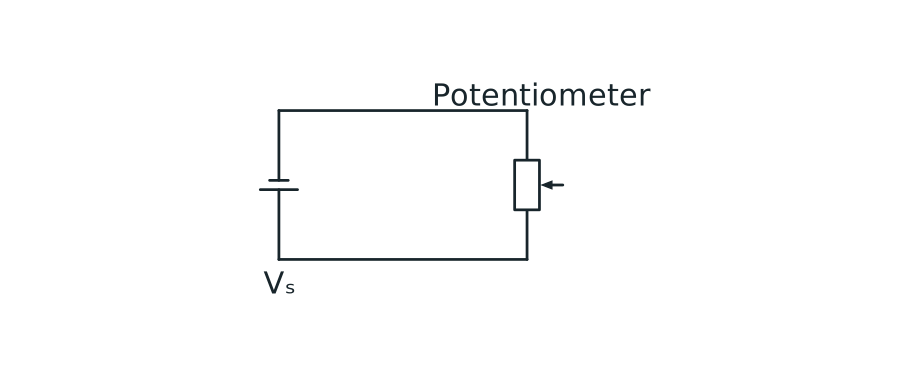
View figure data
| Part | Connection |
|---|---|
| Potentiometer track | Connected across the supply |
| Wiper | Provides the variable output relative to zero volts |
A. How the slider controls the output
A potentiometer is connected across the supply. The slider divides the track into two parts (two resistances). When the slider moves:
- one section becomes longer while the other becomes shorter;
- the resistance of the longer section increases while the resistance of the shorter section decreases;
- the output p.d. changes smoothly between about 0 V and about Vₛ.
For the output shown in the figure, Vₒᵤₜ is measured between the slider and the 0 V end. Moving the slider upwards selects more of the track, so Vₒᵤₜ increases. Moving it downwards selects less of the track, so Vₒᵤₜ decreases.
Potentiometer: output voltage vs slider position (uniform track)
For a uniform potentiometer track, the output voltage is proportional to the slider position.
Scroll across the graph to read all labels.


View figure data
| Slider position from 0 V end (%) | Vout/Vs |
|---|---|
| 0 | 0 |
| 25 | 0.25 |
| 50 | 0.5 |
| 75 | 0.75 |
| 100 | 1 |
The slider can provide a control signal, for example in a volume control. The next lesson uses the same idea with light-dependent resistors and thermistors.
4. Common Mistakes
- Not stating where Vₒᵤₜ is measured—it is always between two points.
- Saying the slider changes the supply voltage. It changes the fraction selected as the output.
- Saying the slider changes the total resistance of the track. It changes the two section resistances, but their total stays the same.
- Forgetting the output reference: at one end Vₒᵤₜ ≈ 0 V, while at the other Vₒᵤₜ ≈ Vₛ for the connection shown.
5. Exam Tips
- Mark the two points between which Vₒᵤₜ is measured before describing a change.
- State the complete chain: slider moves → selected track length and resistance change → output p.d. changes.
- Check the end positions: the output should approach 0 V at one end and Vₛ at the other for the connection shown.
6. Worked Examples
Modelled example 1
Moving the slider upwards
Problem
Study the worked solution
Identify the selected section
Method
State that the section between the 0 V end and the slider becomes longer.Reason
The output points now span more of the resistive track.Working
Selected track length ↑.Link this to the output
Method
State that Vₒᵤₜ increases.Reason
A larger fraction of the supply p.d. is across the selected section.Working
Vₒᵤₜ → Vₛ.
Guided practice 2
Reducing the output
Problem
Choose, then explain
Hints
Hint 1: look at the output points
Hint 2: select less track
View solution step by step
Move towards the reference end
Method
Move the slider towards the 0 V end.Reason
This shortens the selected section and reduces its share of the supply p.d.Working
Selected fraction ↓ ⇒ Vₒᵤₜ↓.
Common misconception 3
Does the whole track resistance change?
Learner response
Separate total resistance from selected resistance
View solution step by step
Keep the whole track fixed
Method
The total track resistance stays the same.Reason
The slider does not change the track material or total length.Working
R_(whole track) = constant.Identify what changes
Method
The slider changes the lengths and resistances of the two track sections.Reason
This changes the fraction of the supply p.d. selected as the output.Working
Slider position → selected fraction → Vₒᵤₜ.
Examiner practice 4
Explain the action of a potentiometer
Examination question
Give the full cause-and-effect chain
View solution step by step
Describe the track change
2 marksMethod
The length and resistance below the slider increase.Reason
The slider moves farther from the lower output point.Working
Lower selected section: length ↑, resistance ↑.State the output change
1 markMethod
The selected section receives a larger fraction of the supply p.d., so Vₒᵤₜ increases.Reason
Potential difference is shared along the resistive track.Working
Vₒᵤₜ↑.
Self-mark with the mark scheme
Compare your response with each mark point. Select a point only when your response contains that evidence.
Self-mark track length, section resistance and output change.
Challenge 5
Output measured from the other end
Connection change
Re-identify the selected track section
Hints
Hint 1: new output points
Hint 2: track length
View solution step by step
Reverse the trend
Method
State that Vₒᵤₜ decreases.Reason
The section between the slider and supply end becomes shorter and selects a smaller fraction of the supply p.d.Working
Upper selected section ↓ ⇒ Vₒᵤₜ↓.
7. Mind Stretchers
Mind stretcher 1: Slider at 25%Extension
A potentiometer is connected across a 6.0 V supply. The slider is at 25% from the 0 V end. Estimate Vₒᵤₜ between the slider and the 0 V end (assume the track is uniform).
Show Answer
If the slider is at 25% from the 0 V end, the output is about 25% of the supply:
Vₒᵤₜ ≈ 0.25 × 6.0 = 1.5 V
Mind stretcher 2: Same movement, opposite resultExtension
Two identical potentiometers have sliders that both move upwards. In circuit A, the output is measured from the 0 V end to the slider. In circuit B, it is measured from the supply end to the slider. Compare the two output changes.
Show Answer
Circuit A’s output increases because the selected section below the slider becomes longer. Circuit B’s output decreases because the selected section above the slider becomes shorter. Slider direction alone is not enough: always identify the two output points.
8. Practice and next step
- On every potentiometer diagram, identify both track ends, the slider and the two points that define Vₒᵤₜ.
- Move the slider in the lab below and predict the output before reading it.
Concept Explorer: Potential Divider Lab
Vary supply, resistor values, sensor placement, and output loading to track voltage trends and checkpoint your divider reasoning.
- Divider Ratio
- Sensor Placement
- Trend Analysis
- Source and Branch Current
Continue with LDR & NTC Thermistor Potential Dividers, where a changing sensor resistance controls the output automatically.
Continue with the next resource in this course.
Course and syllabus information
- Course
- SEC G3 Physics
- Edition
- SEC G3 Physics 2027