Electrical and magnetic investigations
Key idea: Measure current in series and voltage across a component to find its resistance. Reverse a current or move a magnet to test magnetic effects and induction.
Offline pages
Saved on this device only. Connect at least once every 30 days to confirm Premium. Sign-out or a change of account removes saved copies.
Loading guide controls…
Guided lessons · coming soon
Guided lesson
Guided steps
- Connect both meters to measure the same component.
- Follow the resistance calculation and meter connections.
- Calculate both resistances and the joining gradient.
- Calculate both ratios, then choose a better test.
- Read how the wire’s field combines with Earth’s field.
- Reverse the wire’s field and predict the compass direction.
- Compare insertion, holding still and withdrawal.
- Predict the held-still and withdrawal readings.
- Check your meter connections and change one factor at a time.
On this page
You stopped at:
ContinueThree experiments need three different kinds of evidence: paired current and potential difference for resistance, direction and strength comparisons for a current-produced field, and changes in the magnetic field through a coil for induction. Decide which relationship is being tested before changing the apparatus.
Use only the teacher-provided supply, leads and meter ranges. Switch off before changing connections, limit current and avoid overheating wires. Never connect a current meter directly across the supply. Keep strong magnets clear of sensitive equipment and handle their attraction carefully.
Measure resistance with paired readings
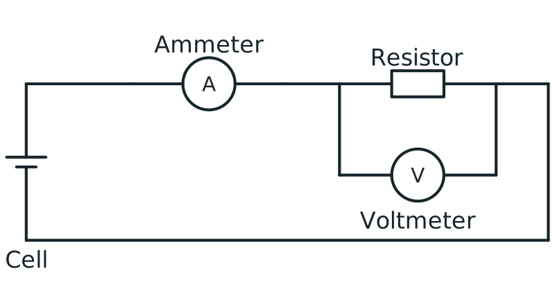
Measure current through the component with an ammeter in series and potential difference across it with a voltmeter in parallel. Choose ranges that include the expected values and check the lead sockets. Record both values for the same operating state.
Voltmeter connection in parallel
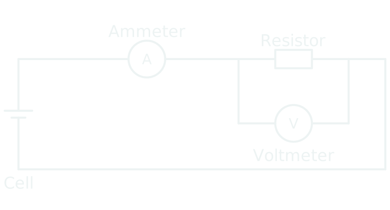
Circuit with ammeter in series and voltmeter connected in parallel across a resistor to measure potential difference.
Scroll across the figure to read all labels.
View figure data
| Part | Connection |
|---|---|
| Ammeter | In series in the main loop |
| Voltmeter | In parallel across the resistor |
| Resistor | In the conducting loop with the cell and ammeter |
For an ohmic component at approximately constant temperature, a straight V-against-I graph through the origin has gradient R. If axes are reversed, its gradient is 1/R. A curved lamp characteristic needs V/I at the stated operating point; a joining-line or tangent gradient is not generally that ratio.
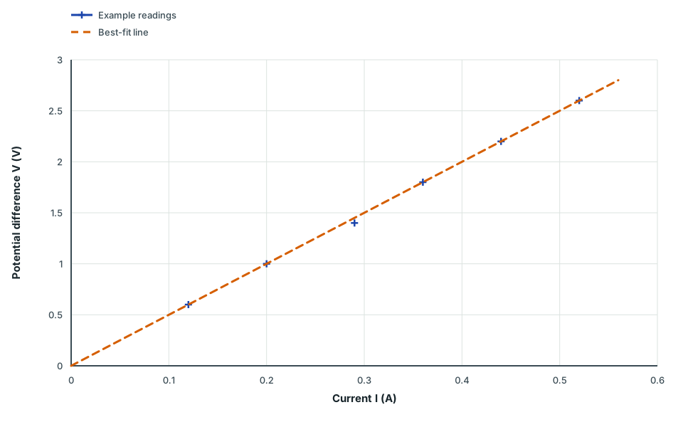
Potential difference against current for a resistor
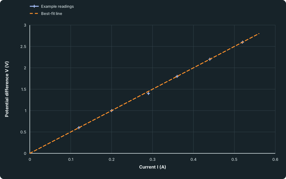
Plotted points of potential difference V in V against current I in A for currents from 0.12 A to 0.52 A, with a dashed best-fit straight line through the origin. The data table lists every plotted value.
Scroll across the figure to read all labels.
View figure data
| Series | Current I (A) | Potential difference V (V) |
|---|---|---|
| Example readings | 0.12 | 0.6 |
| Example readings | 0.20 | 1.0 |
| Example readings | 0.29 | 1.4 |
| Example readings | 0.36 | 1.8 |
| Example readings | 0.44 | 2.2 |
| Example readings | 0.52 | 2.6 |
| Best-fit line | 0.00 | 0.0 |
| Best-fit line | 0.56 | 2.8 |
These are constructed constant-temperature resistor readings. The fitted line passes through (0.10 A, 0.50 V) and (0.50 A, 2.50 V), giving R = (2.50 − 0.50)/(0.50 − 0.10) = 5.0 Ω. Inspect the axis labels and the line, rather than joining the first and last measured points automatically.
Determination of the resistance of a circuit
Method
Connect an ammeter in series and a voltmeter in parallel with the component. Vary potential difference safely, record paired V and I values, and calculate R = V/I. For an ohmic component at constant temperature, use the gradient of a straight V-against-I graph; use the reciprocal gradient for I against V. Limit heating unless temperature is the variable.
Why it works
Measure potential difference across the component and current through it together. At each operating point, R = V/I. For an ohmic component at constant temperature, resistance is the gradient of the straight V-against-I graph; an I-against-V gradient is its reciprocal. Limit heating between readings when temperature is meant to remain constant.
A mistake to avoid: A component's resistance is the voltmeter reading alone.
Check your understanding
Where should each meter be connected, and why should you switch off between readings if temperature is meant to stay constant?
Show answer
Connect the ammeter in series and the voltmeter across the component, and record their paired readings. Switching off between readings limits heating. A temperature change can change resistance, so it would confound a test meant to keep temperature constant.
Worked example 1
Use the voltage across and current through a component
Problem
A component has potential difference 3.6 V across it and current 0.24 A through it at the same moment. Find its resistance and explain the two meter connections.
Show full solution
Trace the connections
Method
Place the ammeter in series and the voltmeter across the component.
Reason
Current must pass through the ammeter; potential difference compares the component’s two terminals.
Working
Answer
The readings must describe the same component and operating state.
Calculate and check
Method
Divide potential difference by current.Reason
R = V/I defines resistance at this operating point.
Working
Answer
R = 3.6 V/0.24 A = 15 Ω. Check: 0.24 A × 15 Ω = 3.6 V.
Quick check
Take several paired readings at controlled temperature to test whether resistance stays constant as voltage changes.
Try it yourself 2
Choose between a ratio and a gradient
Problem
A lamp has paired readings (0.20 A, 1.0 V) and (0.40 A, 3.0 V). Its V-against-I graph is curved. Find the resistance at each point and the gradient joining them. Choose why that gradient is not the lamp’s resistance at either point.
Try before revealing the solution
Show the steps Optional working
Hints
Hint 1
Choose the relevant evidence
Which values belong to one operating point, and which describe a change between points?
Show solution step by step
Use each operating point
Method
Calculate V/I for each matched pair.Reason
Resistance at a point uses the potential difference across and current through the lamp at that point.
Working
Answer
At 0.20 A: R = 1.0/0.20 = 5.0 Ω. At 0.40 A: R = 3.0/0.40 = 7.5 Ω.
Interpret the joining gradient
Method
Calculate ΔV/ΔI and compare it with V/I.Reason
For a curved characteristic, this joining-line gradient does not equal the ratio at either endpoint.
Working
Answer
Joining gradient = (3.0 − 1.0)/(0.40 − 0.20) = 10 Ω. It is neither 5.0 Ω nor 7.5 Ω.
State the straight-line condition
Method
Use a V-against-I gradient for constant resistance only when the graph is straight through the origin under controlled conditions.
Reason
Heating a filament changes its resistance. A lamp is not a fixed-temperature ohmic resistor over this range.
Working
Answer
Limit heating when temperature should be controlled; record paired readings and explain the component’s operating state.
Quick check
For a constant-temperature ohmic resistor, reversing the axes gives gradient 1/R. Always read the axis labels before interpreting a gradient.
Check your understanding 1 Two readings from one resistor
A resistor gives 0.84 V at 0.12 A and 1.40 V at 0.20 A. Calculate its resistance at both points. Choose what these two readings tell you and select a better test of constant resistance.
Show answer
Each ratio gives 7.0 Ω at its measured state. To test other currents, take several safely spaced paired readings, control temperature, repeat where appropriate and inspect a V-against-I graph and measurement uncertainty. Limit heating between readings when it is not the intended variable.
Test the magnetic effect of current
Map the field with a compass at fixed positions around a straight conductor or coil. Record the no-current direction first. Reverse current to test direction while keeping geometry, compass position and current magnitude fixed. Use the right-hand grip rule for the conductor’s contribution.
The compass follows the resultant field, which can include Earth’s field. To compare strength, change current or turns one at a time and keep the observation position and relevant geometry fixed. A different compass distance would confound the comparison.
Investigation of the magnetic effect of current in a conductor
Method
Pass a controlled current through a straight conductor or coil and map the field with a compass at fixed positions. Reverse current to test direction and vary current or turns one at a time to compare field strength.
Why it works
A current produces a magnetic field whose direction reverses with current. Fair strength comparisons keep geometry and measuring position fixed while changing current or coil turns independently.
A mistake to avoid: Current attracts a compass directly, so the compass direction does not represent a field.
Check your understanding
What should happen to the compass direction when the current reverses while every other factor stays fixed?
Show answer
The conductor’s field reverses when the current reverses. Keep the compass position, conductor geometry and current magnitude fixed. The compass follows the resultant field, including Earth’s field, so an exact 180-degree needle rotation is not guaranteed.
Guided practice 3
Use a reversal to test field direction
Problem
At a fixed compass position, the Earth’s field points north and a wire’s field points east. The current is reversed without changing its magnitude. Choose the wire’s new field direction, the quadrant in which the compass’s north end points and whether the needle turns through exactly 180°.
Try before revealing the solution
Hints
Hint 1
Find the decisive relationship
Treat the Earth’s field and the wire’s field as two separate contributions.
Show solution step by step
Apply the direction rule
Method
The wire’s field now points west.Reason
The magnetic field due to the wire reverses when current reverses.
Working
Answer
Wire field: east → west, with unchanged strength.
Compare field and total compass direction
Method
The compass’s north end points between north and west, rather than between north and east.
Reason
The Earth’s northward contribution remains. Adding it to a westward contribution gives a north-west resultant, not the opposite of the original north-east resultant.
Working
Answer
The needle turns through less than 180°. Keep the compass position, wire orientation and current magnitude fixed for this comparison.
Quick check
Reversal provides a direction test. To compare field strength, change one factor at a time and keep the observation position fixed.
Test electromagnetic induction
Connect a coil to a sensitive centre-zero meter. Move a magnet in, hold it still, then move it out, keeping the pole and connections unchanged. Compare direction and size of deflection. Next vary one factor, such as speed, while keeping the others comparable.
A deflection indicates an induced e.m.f. in this circuit while the magnetic field through the coil changes. No steady deflection should remain with the magnet stationary and all other conditions fixed. Reversing motion, the pole, or the meter connections can each reverse the indicated direction; reverse one at a time so the cause is clear.
Investigation of the effects of electromagnetic induction
Method
Connect a coil to a sensitive meter and change the magnetic field through it by moving a magnet or the coil. Compare meter deflection while reversing the motion and varying speed, field strength or number of turns one at a time; no steady deflection should remain when the field through the coil stops changing.
Why it works
An e.m.f. is induced only while the magnetic field through the coil is changing, and it is larger when the field changes faster or the coil has more turns. A magnetic field that is present but not changing induces nothing. Direction tests require one reversal at a time and a zero check with no relative motion.
A mistake to avoid: A stationary magnet inside a coil produces a continuous induced current because the field is strong.
Check your understanding
Why does a stationary magnet give no steady meter deflection, even when it is inside the coil?
Show answer
A stationary magnet with all other conditions fixed gives a magnetic field through the coil that does not change, so there is no steady induced e.m.f. Moving it changes the field through the coil; reversing the motion with the same pole and connections reverses the induced direction.
Spot the mistake 4
Does a strong stationary magnet sustain induction?
Problem
A magnet is moved into a coil connected to a sensitive centre-zero meter; the meter deflects right during insertion. The magnet is held still, then the same pole is pulled out with connections unchanged. A learner predicts a continuous deflection while it is held still because the field is strong. Choose the steady reading while held still, the withdrawal direction and the cause of the induced deflection.
Try before revealing the solution
Show solution step by step
Identify what changes
Method
Compare the magnetic field through the coil while the magnet moves and while it is stationary.
Reason
Induced e.m.f. depends on a change in the field through the coil, not on the presence of a field alone.
Working
Answer
Moving in produces a deflection. Holding the magnet still produces no steady induced deflection, provided other conditions stay fixed.
Reverse one factor
Method
Pull the same pole out with the coil and meter connections unchanged.
Reason
Reversing motion reverses the change in the field through the coil, and so the direction of the induced e.m.f.
Working
Answer
In this trial insertion deflects right, so withdrawal deflects left. Faster motion gives a larger deflection with a suitable responsive meter and comparable motion.
Common mistake
Do not also reverse the magnet’s pole or meter leads when testing the effect of motion reversal. A brief settling movement is not evidence of steady induction.
Common mistakes
- Connecting the voltmeter in series or the ammeter in parallel.
- Leaving the current on between readings, so the component warms and its resistance changes.
- Using the gradient of a curved V–I graph as the resistance. Use R = V/I for each pair of readings.
- Expecting a stationary magnet to induce a steady current. Induction needs a changing magnetic field.
- Changing more than one factor at a time when testing a field direction.
Spotted an error? Report a correction
Syllabus and review details
- SEC G3 Physics 2027 · 2027
Content Structure, PDF page 9; Subject Content, PDF pages 10–28
Last reviewed: