G3 Physics required practical work
Key idea: Learn all 18 G3 Physics practical contexts through reliable methods, worked calculations, diagrams, common mistakes, safety and practical-paper guidance.
Continue where you stopped
The core idea
G3 Physics · Practical paper
Plan and explain every required practical
You do not need to memorise 18 unrelated recipes. Strong practical work follows the same pattern: choose suitable apparatus, change one factor fairly, record trustworthy evidence, process it correctly and explain what the result shows. This lesson applies that pattern to every practical context named for G3 Physics.
What you will be able to do
- write a safe, repeatable method for each of the 18 required contexts;
- identify variables, controls, suitable instruments and useful repeat readings;
- use equations and graphs to turn raw readings into physical quantities;
- spot common method errors and propose improvements that address their cause.
Practical paper: 1 h 50 min, 40 marks and 20% of the course. Section A and Section B are each 20 marks and 55 minutes. Written practice prepares your decisions, but practical competence also requires safe work with real apparatus under your school’s supervision.
The method pattern that works across topics
- Define.State what you will change, measure and keep constant.
- Measure.Name the apparatus, range, resolution and exact reading technique.
- Repeat.Use several well-spaced values and repeats where readings vary.
- Process.Show the calculation or graph that answers the question.
- Evaluate.Link a specific limitation to its effect and a practical improvement.
1. Measure and investigate mechanics
Begin with the quantity you need. The instrument’s range must include the expected value, while its resolution should be fine enough to show useful changes. Then make the force or motion comparison fair.
Swipe the table sideways to see the technique column.
| Quantity | Suitable instrument | Good technique |
|---|---|---|
| Length | Tape, metre rule, digital calipers or digital micrometer | Check zero, align the scale and choose a resolution suited to the object. |
| Time interval | Digital stopwatch, electronic timer or light gates | Use clear start and stop events; time repeated events when possible. |
| Volume | Measuring cylinder or dimensions of a regular solid | Read the bottom of a water meniscus at eye level; remove trapped bubbles. |
| Mass and weight | Electronic balance and spring balance | Zero first and distinguish mass in kg or g from weight in N. |
| Temperature | Laboratory thermometer or temperature probe | Keep the sensor immersed without touching the container; wait for a steady value. |
| Current and voltage | Ammeter and voltmeter | Connect the ammeter in series and voltmeter in parallel; use a suitable range. |
Worked example: density
A 63.0 g solid raises water from 38.0 cm³ to 46.0 cm³. Volume = 8.0 cm³, so density = 63.0 ÷ 8.0 = 7.9 g/cm³ to two significant figures.
Worked example: free fall
For a graph of s against t2, gradient = ½g. A gradient of 4.85 m/s² gives g = 2 × 4.85 = 9.70 m/s².
Worked example: moments
A 3.0 N force acts 0.20 m from a pivot. Its moment is 0.60 N m. A 2.0 N force balances it at 0.30 m on the other side.
Context 1 of 18
Measurements of length, time interval, volume, mass and weight, temperature, current and voltage using the listed instruments
Method
Choose an instrument whose range and resolution suit the quantity, check zero, view the scale correctly, record every value with its unit, and repeat readings when variation is expected.
Why it works
Reliable measurement depends on instrument choice and technique as well as the number recorded. Repeats expose random variation; a zero check and correct viewing position reduce systematic and parallax errors.
Check your understanding
A wire is about 0.35 mm thick. Which instrument would you choose, and what would you check before taking the first reading?
Context 2 of 18
Determination of the density of a liquid, or of a regularly or irregularly shaped solid that sinks in water
Method
Measure mass with an electronic balance, subtracting or taring the container for a liquid and weighing a solid dry. Measure volume directly for a liquid or regular solid, or by water displacement for a sinking irregular solid; calculate density = mass ÷ volume in consistent units.
Why it works
Use the mass and volume of the same sample. For a liquid, subtract or tare the container mass. Weigh a solid dry before immersion; for a sinking irregular solid, subtract the initial water reading from the final reading. Read at eye level, remove trapped bubbles and use consistent units in density = mass ÷ volume.
Check your understanding
How would you find the density of a small stone that sinks? Name the two readings that must be subtracted.
Context 3 of 18
Determination of the value of the acceleration of free fall
Method
Release an object from rest through a measured distance and use electronic timing or light gates to reduce reaction delay. Repeat at several distances or trials, then determine g from s = ½gt² or the gradient of an appropriate graph.
Why it works
A valid determination links a measured displacement to motion from rest. Electronic timing, a consistent release and multiple data points reduce timing uncertainty and test whether the chosen linearised relationship fits.
Check your understanding
If you plot distance against time squared, what does the gradient represent and how do you obtain g from it?
Context 4 of 18
Investigation of the effects of balanced and unbalanced forces
Method
Apply known forces to a trolley or object while controlling mass and resistance. Measure motion before and after changing the resultant force, and compare balanced-force trials with unbalanced-force trials using repeated speed or acceleration data.
Why it works
Balanced forces give zero resultant force and therefore no acceleration; the object may be stationary or move at constant velocity. An unbalanced force changes velocity, so the investigation must measure motion rather than merely observe that forces are present.
Check your understanding
A trolley moves at constant velocity. What does this tell you about its resultant force, and what measurement would show that the forces have become unbalanced?
Context 5 of 18
The principle of moments
Method
Balance a rigid body about a known pivot, measure each force and its perpendicular distance from the pivot, then compare total clockwise and anticlockwise moments. Repeat with different loads and positions while checking that the body is horizontal and stationary.
Why it works
Moment = force × perpendicular distance from the pivot to the force's line of action. Equilibrium requires zero resultant force and equal total clockwise and anticlockwise moments, within measurement uncertainty.
Check your understanding
A force acts at an angle to a ruler. Which distance must you measure before calculating its moment?
Context 6 of 18
Determination of the position of the centre of gravity of a plane lamina
Method
Suspend the plane lamina freely from one point and draw the vertical line indicated by a plumb line. Repeat from at least two well-separated suspension points; the line intersection estimates the centre of gravity, which can be checked by balancing there.
Why it works
When the lamina hangs freely, its centre of gravity lies vertically below the suspension point. Multiple lines provide independent evidence and reveal drawing or alignment uncertainty.
Check your understanding
Why should the two suspension points on a lamina be well separated rather than close together?
2. Investigate thermal physics
Thermal investigations lose energy to the surroundings. Good methods do not pretend this loss is zero: they reduce it, keep conditions matched, collect temperature–time evidence and discuss how remaining loss affects the result.
Worked example: heat capacity
A 0.40 kg block receives 7.2 kJ and warms by 20 °C. Its heat capacity is C = 7200 ÷ 20 = 360 J/°C. Its specific heat capacity is c = 360 ÷ 0.40 = 900 J/(kg °C).
Worked example: latent heat
A heater transfers 12 kJ while 0.050 kg melts at constant temperature. The latent heat for this sample is 12 kJ. Its specific latent heat is l = 12 000 ÷ 0.050 = 2.4 × 10⁵ J/kg.
Context 7 of 18
Investigation of the factors affecting transfer of energy by thermal processes
Method
Change one factor affecting thermal transfer, such as material, thickness, surface or insulation, while keeping geometry, starting temperature, surroundings and measurement intervals matched. Record temperature against time, repeat, and compare rates or temperature changes.
Why it works
A fair thermal-process comparison needs matched thermal conditions and a defined rate measure. Temperature–time curves reveal both the direction and relative rate of transfer; repeats and uncertainty matter when curves are close.
Check your understanding
Two insulated cans start at different temperatures. Why would comparing only their final temperatures be unfair?
Context 8 of 18
Determination of heat capacities of materials
Method
Measure the sample's initial temperature, supply measured electrical energy E = VIt while insulating it, and record the temperature rise. Determine heat capacity from C = E/ΔT. If specific heat capacity is required, also measure mass and use c = C/m = E/(mΔT). Repeat or use a cooling correction to assess heat loss.
Why it works
Heat capacity C describes the whole sample and has unit J/K. Specific heat capacity c is heat capacity per unit mass and has unit J/(kg K). Not all electrical energy heats the sample, so insulation, sensor contact, stirring where suitable and heat-loss evaluation are part of the result.
Check your understanding
Which calculation gives the heat capacity of the whole sample, and when must its mass be included?
Context 9 of 18
Latent heat of substances
Method
During a controlled phase change, measure the energy supplied, for example E = VIt, while checking that the temperature stays near the transition temperature. This energy is the latent heat L for the amount that changes state. To find specific latent heat, also measure that mass and use l = E/m. Account for heat exchange with the surroundings.
Why it works
Latent heat L is the energy transferred while the measured sample changes state without a temperature change. Specific latent heat l is that energy per unit mass. The mass in l = E/m must be the amount that actually changes state during the timed input.
Check your understanding
What should happen to temperature during the phase change, and which mass belongs in the specific-latent-heat calculation?
Check your understanding: Why does using final temperature alone make an insulation comparison unfair when the two samples started at different temperatures?
3. Investigate light and waves
In ray work, accurate reference lines matter as much as the ray itself: mark the boundary, point of incidence and normal before measuring angles. In wave work, measure several wavelengths and several cycles to reduce percentage uncertainty.
Worked example: refraction
If i = 40° and r = 25°, sin i ÷ sin r ≈ 1.52. Repeat at several angles before claiming a constant ratio.
Worked example: wave speed
Six wavelength intervals span 0.48 m, so λ = 0.080 m. At 12 Hz, v = fλ = 12 × 0.080 = 0.96 m/s.
Context 10 of 18
The law of reflection
Method
Direct a narrow ray at a plane mirror, mark the incident and reflected rays, draw the normal at the point of incidence, and measure angles from the normal. Repeat for several incidence angles and compare i with r.
Why it works
The law is tested with paired angles measured from the normal, not the mirror. A narrow ray, fixed mirror line, accurate point marking and repeated angles reduce tracing uncertainty.
Check your understanding
From which line must you measure both the angle of incidence and the angle of reflection?
Context 11 of 18
Determination of the position and characteristics of an optical image formed by a plane mirror or a thin converging lens
Method
For a plane mirror, locate the virtual image by eliminating parallax between its image and a marker. For a thin converging lens, place the object beyond its focal length, focus the real image sharply on a screen, measure object and image distances from the optical centre, and record orientation and size at controlled object positions. An object inside the focal length forms a virtual image, so the screen method does not apply.
Why it works
A plane-mirror image cannot be caught on a screen, so a no-parallax comparison locates it. For a converging lens, place the object beyond the focal length to form a real screen image. Focus sharply and measure object and image distances from the lens's optical centre. An object inside the focal length gives a virtual image that cannot be focused on a screen.
Check your understanding
Why is a screen useful for a converging-lens image but not for a plane-mirror image?
Context 12 of 18
The refraction of light through glass blocks
Method
Trace a narrow ray through a glass block, mark entry and exit points, replace the block outline, and draw normals. Measure incidence and refraction angles from the normal for several trials; if required, compare sin i with sin r.
Why it works
Accurate boundary points and normals are essential because refractive angles are defined at the interface. Multiple angle pairs can test a constant sine ratio for the same two media.
Check your understanding
Which two angles would you record for each ray, and why is one pair of readings not enough?
Context 13 of 18
The principle of total internal reflection
Method
Send a ray through the curved face of a semicircular block so it reaches the flat face from the denser medium. Increase the incidence angle, observe refraction and reflection, and identify the critical angle when the refracted ray travels along the boundary.
Why it works
The curved entry face minimises unwanted refraction when the ray is aimed through the centre. Total internal reflection occurs only from higher to lower refractive index and above the critical angle.
Check your understanding
State the two conditions needed for total internal reflection before describing how to find the critical angle.
Context 14 of 18
The focal length of lenses
Method
Form a sharp image of a distant object on a screen and measure from the lens's optical centre to the screen for an estimate of focal length. Repeat and average; for finite object distances, measure u and v and use the lens relation if required.
Why it works
Light from a distant object reaches the lens nearly parallel, so its sharp real image forms near the focal plane. Sharpness, distance reference and repeated readings dominate the uncertainty.
Check your understanding
Why does a distant object let the lens-to-screen distance estimate the focal length?
Context 15 of 18
Determination of the speed, wavelength and frequency of waves
Method
Measure several wavelengths across a wave pattern and divide by the number of intervals. Determine frequency from counted cycles per measured time, then calculate speed using v = fλ; repeat under fixed medium conditions.
Why it works
Using multiple spatial intervals and cycles reduces percentage uncertainty. Wavelength and frequency must describe the same steady wave in the same medium before they are combined.
Check your understanding
How does measuring across several wavelengths and timing several cycles reduce percentage uncertainty?
Check your understanding: State both conditions needed for total internal reflection, then explain how a semicircular block helps you identify the critical angle.
4. Investigate electricity and magnetism
Circuit readings must be paired: potential difference across the component and current through it at the same moment. Magnetic investigations need a clear direction test—reverse one factor at a time so you can explain the change you observe.
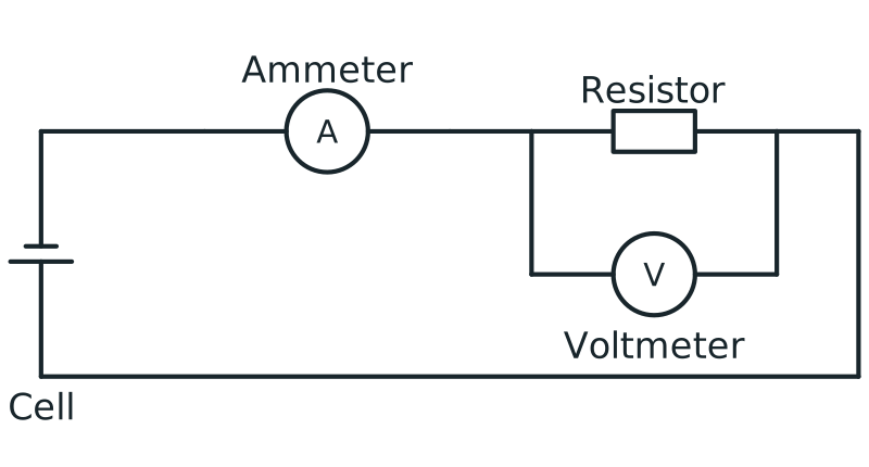
Voltmeter connection in parallel
Circuit with ammeter in series and voltmeter connected in parallel across a resistor to measure potential difference.
View figure data
| Part | Connection |
|---|---|
| Ammeter | In series in the main loop |
| Voltmeter | In parallel across the resistor |
| Resistor | In the conducting loop with the cell and ammeter |
Worked example: resistance
3.6 V across a component produces 0.24 A through it. R = V/I = 3.6/0.24 = 15 Ω. Both readings describe the same component state.
Worked reasoning: induction
Moving a magnet into a coil gives a deflection. Holding it still gives zero. Pulling it out reverses the deflection. The evidence links induced e.m.f. to a change in magnetic flux linkage.
Context 16 of 18
Determination of the resistance of a circuit
Method
Connect an ammeter in series and a voltmeter in parallel with the component. Vary potential difference safely, record paired V and I values, and calculate R = V/I. For an ohmic component at constant temperature, use the gradient of a straight V-against-I graph; use the reciprocal gradient for I against V. Limit heating unless temperature is the variable.
Why it works
Measure potential difference across the component and current through it together. At each operating point, R = V/I. For an ohmic component at constant temperature, resistance is the gradient of the straight V-against-I graph; an I-against-V gradient is its reciprocal. Limit heating between readings when temperature is meant to remain constant.
Check your understanding
Where should each meter be connected, and why should you switch off between readings if temperature is meant to stay constant?
Context 17 of 18
Investigation of the magnetic effect of current in a conductor
Method
Pass a controlled current through a straight conductor or coil and map the field with a compass at fixed positions. Reverse current to test direction and vary current or turns one at a time to compare field strength.
Why it works
A current produces a magnetic field whose direction reverses with current. Fair strength comparisons keep geometry and measuring position fixed while changing current or coil turns independently.
Check your understanding
What should happen to the compass direction when the current reverses while every other factor stays fixed?
Context 18 of 18
Investigation of the effects of electromagnetic induction
Method
Connect a coil to a sensitive meter and change magnetic flux by moving a magnet or coil. Compare meter deflection while reversing motion and varying speed, field strength or turns one at a time; no steady deflection should remain when flux is constant.
Why it works
Induced e.m.f. depends on the rate of change of magnetic flux linkage, not merely the presence of a magnetic field. Direction tests require one reversal at a time and a zero check with no relative motion.
Check your understanding
Why does a stationary magnet give no steady meter deflection, even when it is inside the coil?
5. Practise this
- Explain: choose one context and explain why its main control variable makes the comparison fair.
- Plan: write its apparatus, variables, range of readings, repeats and safety step so another student could follow it.
- Present: draw a results table using headings in the form quantity / unit.
- Analyse: name the graph or calculation, then say how it answers the aim.
- Evaluate: write one limitation as source → effect → specific improvement.
- Check: answer the three opening questions again in complete sentences.
Compare your answer with a strong evaluation
In the free-fall investigation, a short travel time makes any release or timing delay a large percentage of the reading. The calculated value of g may therefore be too high or too low. Use an electronic release and light gates, repeat at several well-spaced distances, and obtain g from the gradient of s against t2. This reduces reaction-time uncertainty and uses all the data.
Exam guidance
Make each method step observable. Name the apparatus, say exactly what is measured, explain how the comparison stays fair and show how the processed evidence supports the conclusion. If the question changes the apparatus, carry over the reasoning rather than forcing a memorised recipe onto the new setup.
Continue with the next resource in this course.
Course and syllabus information
- Course
- SEC G3 Physics
- Edition
- SEC G3 Physics 2027