Resistance, Resistivity and I–V Characteristics
Key idea: Define resistance, use V = IR and R = ρL/A, interpret resistor and filament-lamp I–V characteristics, and explain the temperature effect in metals.
Continue where you stopped
The core idea
On this page
Learning objectives
- Apply resistance and resistivity, interpret I–V characteristics and explain temperature effects.
1. Definitions (Must Know)
A. Resistance, R
The resistance of a component is the ratio of the potential difference across it to the current in it:
R = V/I
Unit: ohm (Ω), where 1 Ω = 1 V A⁻¹.
B. Electrical conductor
An electrical conductor is a material with many mobile charge carriers, so it conducts electricity easily.
In metals, the charge carriers are free electrons.
C. Electrical insulator
An electrical insulator has (almost) no mobile charge carriers, so it does not conduct electricity under normal conditions.
D. Resistivity, ρ
Resistivity, ρ, is a material property that links resistance to geometry:
R = ρL/A
where L is length and A is cross-sectional area.
Unit: Ω m.
2. Key Ideas (What Earns Marks)
- Use V = IR for an ohmic component at constant physical conditions.
- Metals conduct because they have many mobile electrons; insulators have very few mobile carriers.
- Resistivity is a material property (depends on material and temperature).
- For a uniform wire at fixed temperature:
- R ∝ L
- R ∝ 1/A
- Typical metals: resistivity increases with temperature (more collisions).
- The gradient of an I–V graph is I/V = 1/R, not R.
Don’t say “electrons slow down so current decreases” unless the circuit conditions are stated. In many questions, the supply voltage is fixed, so increased resistivity increases R and reduces current via I = V/R.
3. Detailed Explanations
A. Ohmic and non-ohmic I–V characteristics
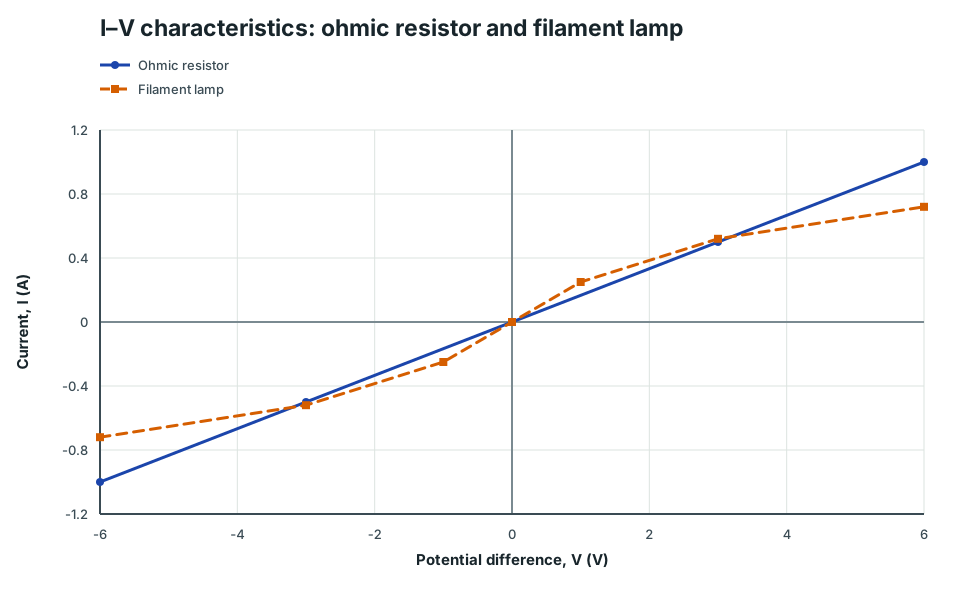
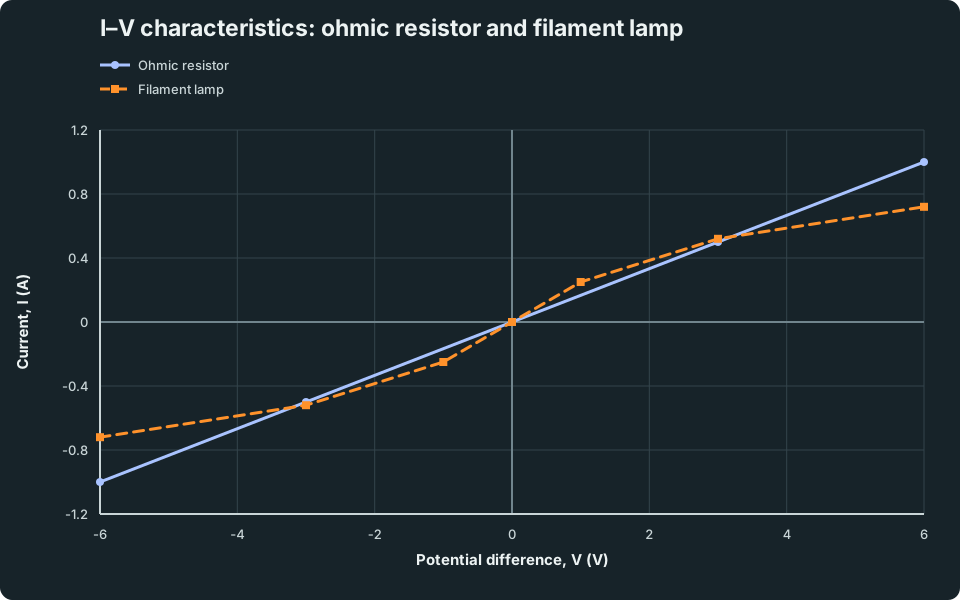
An ohmic resistor at constant temperature has I ∝ V, so its I–V graph is a straight line through the origin. A filament lamp heats as current increases; its resistance rises, so the graph’s gradient decreases at larger |V|.
I–V characteristics: ohmic resistor and filament lamp
Current against potential difference for an ohmic resistor and a filament lamp, showing the lamp curve becoming less steep as its temperature rises.
Scroll across the graph to read all labels.
View figure data
| Series | Potential difference, V (V) | Potential difference, V uncertainty | Current, I (A) | Current, I uncertainty |
|---|---|---|---|---|
| Ohmic resistor | -6 | -1 | ||
| Ohmic resistor | -3 | -0.5 | ||
| Ohmic resistor | 0 | 0 | ||
| Ohmic resistor | 3 | 0.5 | ||
| Ohmic resistor | 6 | 1 | ||
| Filament lamp | -6 | -0.72 | ||
| Filament lamp | -3 | -0.52 | ||
| Filament lamp | -1 | -0.25 | ||
| Filament lamp | 0 | 0 | ||
| Filament lamp | 1 | 0.25 | ||
| Filament lamp | 3 | 0.52 | ||
| Filament lamp | 6 | 0.72 |
At an operating point, resistance is always R = V/I. It is not generally found from the reciprocal tangent gradient for a non-linear component.
B. Conduction in metals (drift + collisions)
In a metal, free electrons move randomly. When a potential difference is applied, an electric field is set up and electrons gain a small net drift velocity.
Electrons frequently collide with lattice ions. These collisions are why:
- energy is transferred to the lattice (heating),
- the drift speed is small even when the current is large (because number density is huge).
Link to the drift current equation:
I = nAv|q|
(see Drift Velocity & Current).
C. Why insulators do not conduct (in this model)
In an insulator, electrons are tightly bound to atoms, so there are very few mobile charge carriers.
With no carriers to drift, current is (approximately) zero.
D. Resistivity and geometry
For a uniform wire:
R = ρL/A
Interpretation:
- longer wire ⇒ more collisions ⇒ larger R,
- thicker wire (larger A) ⇒ more parallel paths ⇒ smaller R.
E. Temperature dependence for metals
For typical metals, increasing temperature increases lattice vibration.
This increases collision frequency, reducing electron mobility (for a given field), so resistivity ρ increases.
In filament lamps, the temperature rise can be large, so R increases significantly as current increases (non-ohmic behaviour).
4. Common Mistakes
- Mixing up resistivity ρ (Ω m) with resistance R (Ω).
- Calling the gradient of an I–V graph the resistance. For axes I against V, the straight-line gradient is 1/R.
- Using A in mm² without converting to m².
- Claiming “insulators have no electrons” (they do; the issue is that electrons are not free to move).
- Forgetting that ρ usually depends on temperature.
5. Exam Tips
- If a question changes wire geometry: R₂/R₁ = (ρ₂/ρ₁)(L₂/L₁)A₁/A₂ For the same material at the same temperature, ρ₂ = ρ₁.
- If you are given diameter d: A = π(d/2)²
- For “temperature effect” explanations in metals: use “more lattice vibration → more collisions → lower mobility → higher ρ”.
6. Worked Examples
Modelled example 1
Resistance from resistivity
Problem
Study the worked solution
Select the material-and-geometry relation
Method
Use R = ρ L/A.Reason
Resistivity describes the material; length and area describe the sample geometry.Working
R = (1.7 × 10⁻⁸)2.0/(1.0 × 10⁻⁶)Evaluate
Method
Obtain 3.4 × 10⁻² Ω.Reason
All quantities are already in SI units.Working
R = 3.4 × 10⁻² Ω
Guided practice 2
Comparing two wires (same material)
Problem
Try this before viewing the solution
Hints
Hint 1: cancel the shared property
Hint 2: form the ratio
View solution step by step
Cancel resistivity
Method
Compare only length and area factors.Reason
ρ₂/ρ₁ = 1 under the stated conditions.Working
R₂/R₁ = (L₂/L₁)A₁/A₂Apply both changes
Method
Multiply the factor two by the reciprocal of one-half.Reason
Resistance increases with length but decreases with area.Working
R₂/R₁ = 2(1/(1/2)) = 4
Common misconception 3
Finding resistivity
Learner claim
Try this before viewing the solution
View solution step by step
Rearrange before substituting
Method
Use ρ = RA/L.Reason
Multiplying R = ρ L/A by A/L isolates ρ.Working
ρ = ((0.80)(2.0 × 10⁻⁷))/5.0Evaluate with the material unit
Method
Obtain 3.2 × 10⁻⁸ Ω m.Reason
Resistivity has unit ohm metre, unlike resistance.Working
ρ = 3.2 × 10⁻⁸ Ω m
Examiner practice 4
Effect of halving the diameter (same material)
Examination question
Try this before viewing the solution
View solution step by step
Relate diameter to area
1 markMethod
Square the diameter factor.Reason
A = π d²/4.Working
A₂/A₁ = (1/2)² = 1/4Relate resistance to area
1 markMethod
Use R ∝ 1/A.Reason
Resistivity and length are unchanged.Working
R₂/R₁ = A₁/A₂State the factor
1 markMethod
Conclude that resistance quadruples.Reason
Taking the reciprocal of one-quarter gives four.Working
R₂/R₁ = 4
Self-mark with the mark scheme
Compare your response with each mark point. Select a point only when your response contains that evidence.
Self-mark area factor, inverse relationship and ratio.
Challenge 5
Current change when resistivity changes (fixed voltage)
Independent transfer
Try this before viewing the solution
Hints
Hint 1: hold geometry fixed
View solution step by step
Transfer the material change to resistance
Method
Double the resistance.Reason
With fixed L and A, R ∝ ρ.Working
R₂ = 2R₁Transfer resistance to current
Method
Halve the current.Reason
At fixed V, I = V/R.Working
I₂/I₁ = R₁/R₂ = 1/2
7. Mind Stretchers
Mind stretcher 1: Filament lamp resistance increaseExtension
Explain why a filament lamp’s resistance increases as current increases.
Show Answer
Larger current causes more heating (P = I²R). The filament temperature rises, lattice vibration increases, collision frequency increases, so resistivity (and hence resistance) increases.
Mind stretcher 2: Stretching a wire (constant volume)Extension
A wire of fixed resistivity is stretched so its length doubles. Assuming volume stays constant, what happens to its resistance?
Show Answer
If volume AL is constant, doubling L halves A.
Then:
R = ρL/A ⇒ R₂/R₁ = (L₂/L₁)A₁/A₂ = (2)(1/(1/2)) = 4
So resistance quadruples.
Mind stretcher 3: Optional (Enrichment)Extension
A. Other charge carriers (beyond this lesson)
Not all conductors use electrons:
- electrolytes conduct via positive and negative ions,
- gases conduct when ionised.
Continue with Semiconductors and NTC Thermistors.
Continue with the next resource in this course.
Course and syllabus information
- Course
- GCE A-Level H2 Physics
- Edition
- GCE A-Level H2 Physics 2027