D.C. Circuits
A Level D.C. Circuits hub covering circuit diagrams, resistance and I–V curves, internal resistance, resistor networks, potential dividers, capacitors and RC transients.
Learning goals
- Recall circuit symbols and draw or interpret circuit diagrams.
- Draw circuit diagrams containing sources, switches, resistors, meters, lamps, thermistors, light-dependent resistors and diodes.
- Apply resistance and resistivity, interpret I–V characteristics and explain temperature effects.
- Analyse e.m.f., terminal potential difference and internal resistance in real sources.
- Analyse series, parallel and potential-divider resistor networks.
- Combine capacitors in series and parallel.
- Analyse charging and discharging in RC circuits using the time constant.
D.C. Circuits turns energy-per-charge ideas into a systematic model of components and networks. Start by reading the diagram correctly, then decide what is shared: current in series, potential difference in parallel, or time dependence in an RC circuit.
Prerequisites: A Level Currents, O Level D.C. Circuits, and capacitance from Electric Fields.
Route: symbols → resistance and I–V curves → internal resistance → resistor networks and dividers → capacitor combinations → RC transients.
After this hub: take the D.C. Circuits Quiz, then the D.C. Circuits Structured Set.
Lessons
Work through these lessons in order.
- Circuit symbols and diagrams
- Resistance, resistivity, I–V characteristics and temperature
- Internal resistance, terminal p.d. and output power
- Series, parallel and potential-divider networks
- Capacitors in series and parallel
- Charging, discharging and time constant
- Circuit Symbols and Diagrams
Recall A Level circuit symbols and draw or interpret diagrams containing sources, meters, resistors, sensors, diodes and capacitors.
- Resistance, Resistivity and I–V Characteristics
Define resistance, use V = IR and R = ρL/A, interpret resistor and filament-lamp I–V characteristics, and explain the temperature effect in metals.
- Semiconductors and NTC Thermistors
Explain why semiconductor resistivity decreases with temperature and interpret the I–V characteristics of an NTC thermistor and semiconductor diode.
- Internal Resistance
Relate e.m.f., terminal potential difference and internal resistance using V = ε − Ir, and solve power/efficiency problems for sources (A Level Physics).
- Resistors in Series and Parallel
Calculate combined resistance for series and parallel resistor networks and solve one-source circuits using current and potential-difference relationships.
- Potential Divider Principle
Use the potential divider relationship to find output voltages in series resistor networks, including thermistor and LDR sensing circuits (A Level Physics).
- Capacitors In Series And Parallel
Find the combined capacitance of capacitors in series and parallel, and solve charge/voltage distribution problems (A Level Physics).
- RC Circuits (Charging & Discharging)
Use τ = RC and exponential equations to describe and calculate how charge, current and capacitor voltage change in RC charging/discharging circuits (A Level Physics).
Revision
Quick reference
| Model | Relationship | Fast check |
|---|---|---|
| Resistance | R = V/I | on an I–V graph, straight-line gradient is 1/R |
| Resistivity | R = ρ L/A | use L in m and A in m² |
| Real source | V = E-Ir | terminal p.d. falls as delivered current rises |
| Series resistors | R_eq = ∑ R | result exceeds every resistor |
| Parallel resistors | 1/R_eq = ∑(1/R) | result is below the smallest branch |
| Potential divider | Vₒᵤₜ = VₛR₂/(R₁ + R₂) | formula assumes output is across R₂ |
| Parallel capacitors | C_eq = ∑ C | capacitance increases |
| Series capacitors | 1/C_eq = ∑(1/C) | capacitance falls below the smallest |
| RC time constant | τ = RC | after τ, decay has 1/e ≈ 0.37 remaining |
Resistor network checkpoint
Before calculating, mark nodes. Physical position on the page does not determine whether components are in series or parallel.
RC graph checkpoint
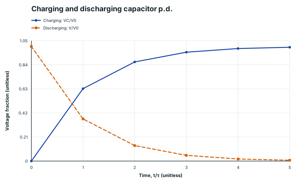
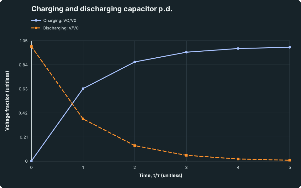
Charging and discharging capacitor p.d.
Normalised capacitor potential difference against time in units of the time constant for charging and discharging.
Scroll across the graph to read all labels.
View figure data
| Time, t/τ (unitless) | Charging: VC/V0 | Discharging: V/V0 |
|---|---|---|
| 0 | 0 | 1 |
| 1 | 0.632 | 0.368 |
| 2 | 0.865 | 0.135 |
| 3 | 0.95 | 0.05 |
| 4 | 0.982 | 0.018 |
| 5 | 0.993 | 0.007 |
Exam traps
- Resistance is not always constant. Use R = V/I at the operating point for a non-ohmic component.
- Graph axes matter. For current on the vertical axis and p.d. on the horizontal axis, an ohmic gradient is 1/R.
- Topology beats appearance. Parallel components must share both end nodes.
- Sensor position controls output direction. State which divider component Vₒᵤₜ is across.
- Resistor and capacitor combination rules are opposite. Use a limiting check.
- Charging current decays. Capacitor charge and p.d. rise, but current falls from its initial value.
Practice
Use the quiz to diagnose a weak outcome, then complete one component-characteristic question and one network or RC question.
Optional extension after the core route: Kirchhoff’s First Law and Kirchhoff’s Second Law provide a consistent method for more complex networks, but the laws are not named explicitly in syllabus 9478.
Next hub: Electromagnetic Forces
Continue with the next resource in this course.
Course and syllabus information
- Course
- GCE A-Level H2 Physics
- Edition
- GCE A-Level H2 Physics 2027