Potential Divider Principle
Key idea: Use the potential divider relationship to find output voltages in series resistor networks, including thermistor and LDR sensing circuits (A Level Physics).
Continue where you stopped
The core idea
On this page
Learning objectives
- Analyse series, parallel and potential-divider resistor networks.
1. Definitions (Must Know)
A. Potential divider
A potential divider is a series combination of resistors used to produce a fraction of the input potential difference.
B. Output voltage, Vₒᵤₜ
Vₒᵤₜ is the potential difference across a chosen component (often across R₂).
2. Key Ideas (What Earns Marks)
- For an unloaded two-resistor divider with fixed input Vᵢₙ: Vₒᵤₜ = VᵢₙR₂/(R₁ + R₂) if the output is taken across R₂.
- Voltage divides in proportion to resistance because the same current flows through series components: V₁:V₂ = R₁:R₂
- Sensors are often used as one resistor:
- NTC thermistor: resistance decreases when temperature increases
- LDR: resistance decreases when light intensity increases
Write “Vₒᵤₜ across R₂” (or across R₁) before using the formula.
3. Detailed Explanations
A. Derivation of the divider formula
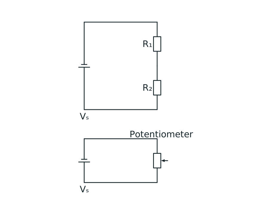
Fixed and variable potential-divider circuits
The upper circuit has resistors R1 and R2 in series across a supply, with output voltage measured across the lower resistor R2. The lower circuit has a three-terminal potentiometer across a supply, with output measured from its slider to the zero-volt end.
View figure data
| Circuit | Connection |
|---|---|
| Fixed divider | R₁ and R₂ are in series; output is across R₂ |
| Variable divider | The potentiometer track is across the supply; output is taken from its wiper |
For series resistors:
I = Vᵢₙ/(R₁ + R₂)
If Vₒᵤₜ is across R₂:
B. How changing resistance changes Vₒᵤₜ
For output across R₂:
- increasing R₂ increases Vₒᵤₜ
- increasing R₁ decreases Vₒᵤₜ
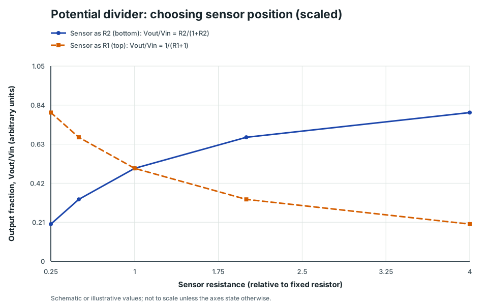
Potential divider: choosing sensor position (scaled)
Two divider curves showing how Vout/Vin changes with sensor resistance depending on whether the sensor is placed at R1 (top) or R2 (bottom).
Scroll across the graph to read all labels.
View figure data
| Sensor resistance (relative to fixed resistor) | Sensor as R2 (bottom): Vout/Vin = R2/(1+R2) | Sensor as R1 (top): Vout/Vin = 1/(R1+1) |
|---|---|---|
| 0.25 | 0.2 | 0.8 |
| 0.5 | 0.333 | 0.667 |
| 1 | 0.5 | 0.5 |
| 2 | 0.667 | 0.333 |
| 4 | 0.8 | 0.2 |
C. Sensor dividers (NTC thermistor / LDR)
If you replace one resistor with a sensor, Vₒᵤₜ becomes a function of temperature or light.
Typical exam task: choose whether to place the sensor as R₁ or R₂ so that Vₒᵤₜ increases when temperature/light increases.
D. Loading the output
The simple divider formula assumes that the output is unloaded, or that the connected device has a resistance much larger than the divider resistances. If a load R_L is connected across R₂, it is in parallel with R₂:
R_eq = R₂∥ R_L = R₂R_L/(R₂ + R_L)
Replace R₂ by R_eq before applying the divider relationship:
Vₒᵤₜ = VᵢₙR_eq/(R₁ + R_eq)
For a finite passive load, R_eq < R₂, so the loaded output is lower than the unloaded output. Current through R₁ now splits between R₂ and R_L; it is not correct to treat the same current as flowing through all three resistors.
If R_L is very large, R₂∥ R_L ≈ R₂ and the unloaded result is recovered. This model assumes a fixed ideal input voltage and negligible wire resistance.
4. Common Mistakes
- Using the formula but taking Vₒᵤₜ across the wrong resistor.
- Forgetting the divider only holds in this simple form when the output is not significantly loaded by another component.
- Not stating the thermistor/LDR trend (NTC thermistor and LDR both decrease resistance when the stimulus increases).
5. Exam Tips
- If the question is qualitative, use ratios: Vₒᵤₜ ∝ R₂/(R₁ + R₂) and discuss what happens as the sensor resistance changes.
- If the question is quantitative, compute Vₒᵤₜ from the formula after converting units.
6. Worked Examples
Modelled example 1
Simple divider calculation
Problem
Study the worked solution
Identify the output resistor
Method
Place R₂ in the numerator.Reason
The output p.d. is measured across R₂.Working
Vₒᵤₜ = VᵢₙR₂/(R₁ + R₂)Calculate the divider fraction
Method
Use one-quarter of the input.Reason
Resistance units cancel in the ratio.Working
Vₒᵤₜ = 121.0/(3.0 + 1.0) = 3.0 V
Guided practice 2
Thermistor placement (qualitative)
Problem
Try this before viewing the solution
Hints
Hint 1: state the sensor trend
Hint 2: track the divider fraction
View solution step by step
Place the NTC in the top arm
Method
Use the thermistor as R₁.Reason
Its falling resistance reduces the denominator without reducing the output-arm numerator.Working
Vₒᵤₜ = VᵢₙR₂/(R₁ + R₂)Track the temperature change
Method
Conclude that output rises.Reason
T↑ makes NTC R₁↓, increasing the fraction across fixed R₂.Working
T↑ ⇒ R₁↓ ⇒ Vₒᵤₜ↑.
Common misconception 3
Output taken across the top resistor
Learner claim
Try this before viewing the solution
View solution step by step
Match numerator to output terminals
Method
Use R₁ in the numerator.Reason
The requested p.d. is across the top resistor.Working
Vₒᵤₜ = VᵢₙR₁/(R₁ + R₂)Evaluate
Method
Obtain 6.0 V.Reason
R₁ is two-thirds of the series total.Working
Vₒᵤₜ = 9.02.0/(2.0 + 1.0) = 6.0 V
Examiner practice 4
Sensor value changes (numerical)
Examination question
Try this before viewing the solution
View solution step by step
Use the output-arm divider form
1 markMethod
Place LDR resistance in the numerator.Reason
Output is across R₂.Working
Vₒᵤₜ = 5.0R₂/(1.0 + R₂)Calculate the dark output
1 markMethod
Use R₂ = 4.0 kΩ.Reason
The resistance units cancel within the ratio.Working
V_dark = 5.04.0/(1.0 + 4.0) = 4.0 VCalculate the bright output
1 markMethod
Use R₂ = 1.0 kΩ.Reason
Light lowers LDR resistance.Working
V_bright = 5.01.0/(1.0 + 1.0) = 2.5 VState the trend
1 markMethod
Output falls as light intensity rises.Reason
The output is measured across the decreasing LDR resistance.Working
4.0 V → 2.5 V.
Self-mark with the mark scheme
Compare your response with each mark point. Select a point only when your response contains that evidence.
Self-mark relation, two values and trend.
Challenge 5
LDR placement for “Vout increases with light”
Independent transfer
Try this before viewing the solution
Hints
Hint 1: work backwards from the required output
View solution step by step
Choose the top arm
Method
Place the LDR as R₁.Reason
Then the output-arm resistance R₂ remains fixed.Working
Vₒᵤₜ = VᵢₙR₂/(R_LDR + R₂)Follow the stimulus
Method
Conclude that output rises with illumination.Reason
Light lowers R_LDR, reducing the denominator.Working
Light ↑ ⇒ R₁↓ ⇒ Vₒᵤₜ↑.
Challenge 6
Loaded divider calculation
Independent boundary transfer
Try this before viewing the solution
Hints
Hint 1: replace the loaded lower arm
View solution step by step
Find the unloaded output
Method
Use R₂ as the lower arm.Reason
No load yet changes the divider.Working
V_unloaded = 124.0/(2.0 + 4.0) = 8.0 VReduce the loaded lower arm
Method
Combine R₂ and R_L in parallel.Reason
The load connects across the same output nodes.Working
R_eq = 4.0∥4.0 = 2.0 kΩFind the loaded output
Method
Use R_eq in the divider.Reason
It is the effective resistance across the output terminals.Working
V_loaded = 122.0/(2.0 + 2.0) = 6.0 V
7. Mind Stretchers
Mind stretcher 1: Voltmeter loadingExtension
A 9.0 V divider uses R₁ = R₂ = 10 kΩ. A voltmeter with resistance 10 kΩ is connected across R₂. Compare the ideal unloaded output with the voltmeter reading.
Show Answer
Without the meter:
Vₒᵤₜ = 9.010/(10 + 10) = 4.5 V
The meter is in parallel with R₂:
R_eq = 10∥10 = 5.0 kΩ
So the reading is:
Vₒᵤₜ = 9.05.0/(10 + 5.0) = 3.0 V
The meter resistance is not large compared with the divider resistances, so it significantly loads the output.
Mind stretcher 2: When does the simple divider formula fail?Extension
Give one practical condition under which Vₒᵤₜ = VᵢₙR₂/(R₁ + R₂) does not predict the measured output accurately, and explain why.
Show Answer
If the output is connected to a device with comparable or low resistance (a heavy load), that device is effectively in parallel with R₂.
This changes the effective resistance across the output and therefore changes the divider ratio, so the simple two-resistor formula no longer applies.
Mind stretcher 3: Variable-divider terminologyExtension
A three-terminal potentiometer used as a variable divider has a resistive track connected across the supply and a movable slider that selects Vₒᵤₜ. Do not confuse this with a slide-wire null-method potentiometer, which is a different measurement circuit.
Mind stretcher 4: Simulation Bridge: Potential Divider LabExtension
Concept Explorer: Potential Divider Lab
Vary supply, resistor values, sensor placement, and output loading to track voltage trends and checkpoint your divider reasoning.
- Divider Ratio
- Sensor Placement
- Trend Analysis
- Source and Branch Current
Apply the principle in the Potential Divider Lab. Open More controls, enable Output loading, and compare the unloaded output with different load resistances.
Continue with the next resource in this course.
Course and syllabus information
- Course
- GCE A-Level H2 Physics
- Edition
- GCE A-Level H2 Physics 2027