Potential dividers with thermistors and LDRs
Key idea: An LDR's resistance falls in brighter light, and an NTC thermistor's falls as it warms. In a potential divider, the sensor's share of supply voltage falls and the fixed resistor's rises.
Offline pages
Saved on this device only. Connect at least once every 30 days to confirm Premium. Sign-out or a change of account removes saved copies.
Loading guide controls…
Guided lessons · coming soon
Guided lesson
Guided steps
- Derive the voltage share and identify which resistor belongs in the numerator.
- Connect sensor resistance change to the measured voltage share.
- Predict the output direction for both thermistor positions before opening the lab.
- Set both sensor arrangements and compare their outputs while warming.
- Record both trends and explain them using the arm resistances.
- Follow sensor placement and calculate the cold and warm outputs.
- Calculate both outputs with the LDR in the lower arm.
- Choose the sensor position and find both outputs across the upper arm.
- Infer the thermistor resistance from voltage shares and explain the warming trend.
On this page
You stopped at:
ContinueA thermistor’s resistance changes with temperature and an LDR’s with light, but a control circuit needs a changing voltage, not a changing resistance. Put the sensor in series with a fixed resistor across a supply and the p.d. across either one changes with the temperature or the light. That arrangement is a potential divider.
The potential divider
Two resistors R₁ and R₂ in series across a supply p.d. Vₛ carry the same current, I = Vₛ/(R₁ + R₂). The p.d. across R₂ is then
The supply p.d. is shared in the ratio of the resistances: the larger resistor takes the larger share. The resistance on top of the fraction is the one the output is measured across. This assumes no current is drawn from the output.
Fixed and variable potential-divider circuits
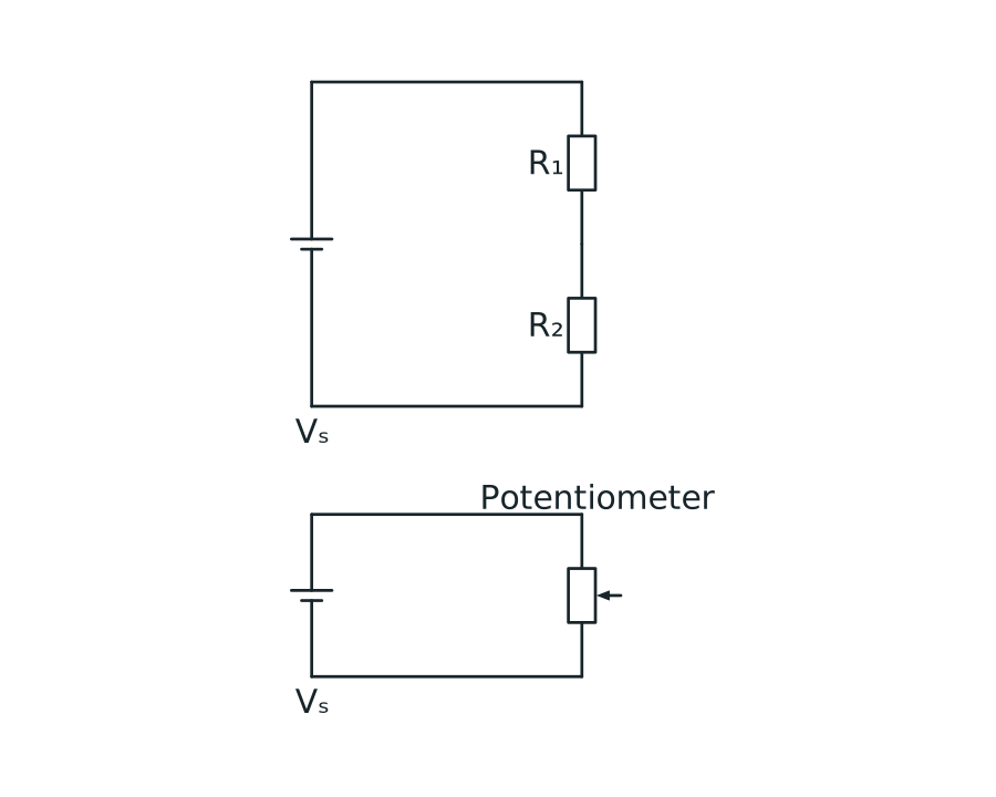
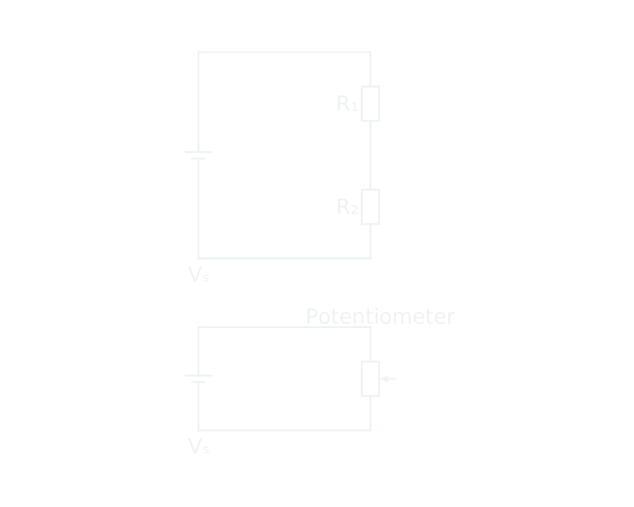
The upper circuit has resistors R1 and R2 in series across a supply, with output voltage measured across the lower resistor R2. The lower circuit has a three-terminal potentiometer across a supply, with output measured from its slider to the zero-volt end.
Scroll across the figure to read all labels.
View figure data
| Circuit | Connection |
|---|---|
| Fixed divider | R₁ and R₂ are in series; output is across R₂ |
| Variable divider | The potentiometer track is across the supply; output is taken from its wiper |
Sensors in a divider
The resistance of an NTC thermistor falls as its temperature rises. The resistance of an LDR falls as the light falling on it gets brighter.
Suppose the output is measured across the lower resistor:
- With the sensor in the upper position, its resistance falls as the temperature or light increases, so the lower, fixed resistor takes a larger share: the output rises.
- With the sensor in the lower position, its own share falls: the output falls.
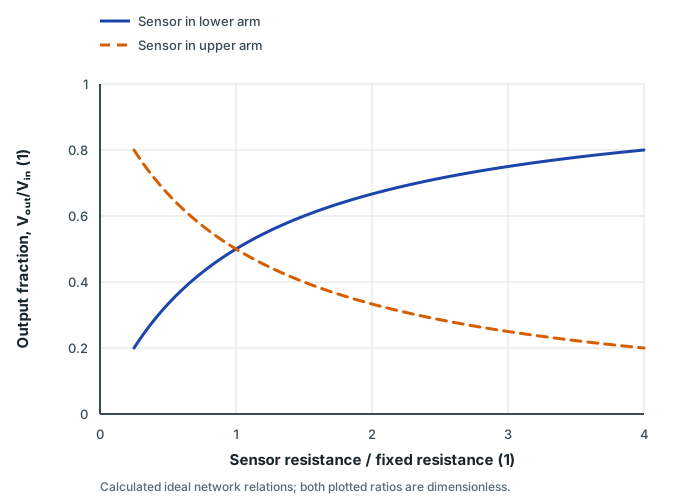
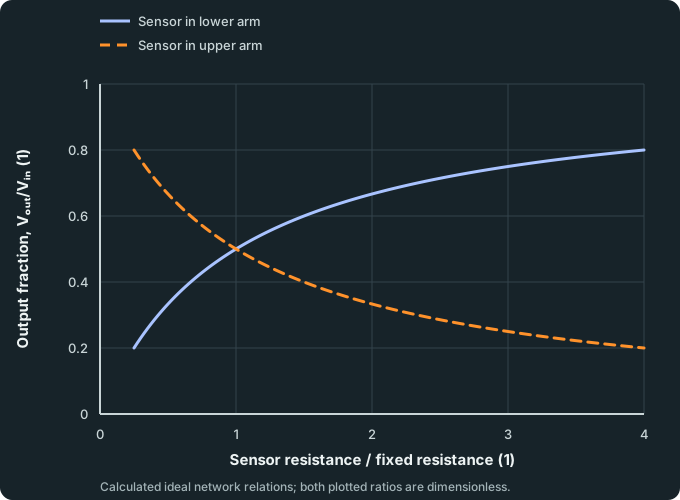
So the position of the sensor decides whether the output rises or falls. The graph shows how the output depends on the ratio of the two resistances; it does not tell you the temperature or the light level without the sensor’s own calibration.
Sensor placement in a potential divider
Two divider curves showing how Vₒᵤₜ/Vᵢₙ changes with sensor resistance depending on whether the sensor is placed at R₁ (top) or R₂ (bottom).
Scroll across the figure to read all labels.
View figure data
| Sensor resistance / fixed resistance (1) | Sensor in lower arm | Sensor in upper arm |
|---|---|---|
| 0.250 | 0.2000 | 0.8000 |
| 0.275 | 0.2157 | 0.7843 |
| 0.300 | 0.2308 | 0.7692 |
| 0.325 | 0.2453 | 0.7547 |
| 0.350 | 0.2593 | 0.7407 |
| 0.375 | 0.2727 | 0.7273 |
| 0.400 | 0.2857 | 0.7143 |
| 0.425 | 0.2982 | 0.7018 |
| 0.450 | 0.3103 | 0.6897 |
| 0.475 | 0.3220 | 0.6780 |
| 0.500 | 0.3333 | 0.6667 |
| 0.525 | 0.3443 | 0.6557 |
| 0.550 | 0.3548 | 0.6452 |
| 0.575 | 0.3651 | 0.6349 |
| 0.600 | 0.3750 | 0.6250 |
| 0.625 | 0.3846 | 0.6154 |
| 0.650 | 0.3939 | 0.6061 |
| 0.675 | 0.4030 | 0.5970 |
| 0.700 | 0.4118 | 0.5882 |
| 0.725 | 0.4203 | 0.5797 |
| 0.750 | 0.4286 | 0.5714 |
| 0.775 | 0.4366 | 0.5634 |
| 0.800 | 0.4444 | 0.5556 |
| 0.825 | 0.4521 | 0.5479 |
| 0.850 | 0.4595 | 0.5405 |
| 0.875 | 0.4667 | 0.5333 |
| 0.900 | 0.4737 | 0.5263 |
| 0.925 | 0.4805 | 0.5195 |
| 0.950 | 0.4872 | 0.5128 |
| 0.975 | 0.4937 | 0.5063 |
| 1.000 | 0.5000 | 0.5000 |
| 1.025 | 0.5062 | 0.4938 |
| 1.050 | 0.5122 | 0.4878 |
| 1.075 | 0.5181 | 0.4819 |
| 1.100 | 0.5238 | 0.4762 |
| 1.125 | 0.5294 | 0.4706 |
| 1.150 | 0.5349 | 0.4651 |
| 1.175 | 0.5402 | 0.4598 |
| 1.200 | 0.5455 | 0.4545 |
| 1.225 | 0.5506 | 0.4494 |
| 1.250 | 0.5556 | 0.4444 |
| 1.275 | 0.5604 | 0.4396 |
| 1.300 | 0.5652 | 0.4348 |
| 1.325 | 0.5699 | 0.4301 |
| 1.350 | 0.5745 | 0.4255 |
| 1.375 | 0.5789 | 0.4211 |
| 1.400 | 0.5833 | 0.4167 |
| 1.425 | 0.5876 | 0.4124 |
| 1.450 | 0.5918 | 0.4082 |
| 1.475 | 0.5960 | 0.4040 |
| 1.500 | 0.6000 | 0.4000 |
| 1.525 | 0.6040 | 0.3960 |
| 1.550 | 0.6078 | 0.3922 |
| 1.575 | 0.6117 | 0.3883 |
| 1.600 | 0.6154 | 0.3846 |
| 1.625 | 0.6190 | 0.3810 |
| 1.650 | 0.6226 | 0.3774 |
| 1.675 | 0.6262 | 0.3738 |
| 1.700 | 0.6296 | 0.3704 |
| 1.725 | 0.6330 | 0.3670 |
| 1.750 | 0.6364 | 0.3636 |
| 1.775 | 0.6396 | 0.3604 |
| 1.800 | 0.6429 | 0.3571 |
| 1.825 | 0.6460 | 0.3540 |
| 1.850 | 0.6491 | 0.3509 |
| 1.875 | 0.6522 | 0.3478 |
| 1.900 | 0.6552 | 0.3448 |
| 1.925 | 0.6581 | 0.3419 |
| 1.950 | 0.6610 | 0.3390 |
| 1.975 | 0.6639 | 0.3361 |
| 2.000 | 0.6667 | 0.3333 |
| 2.025 | 0.6694 | 0.3306 |
| 2.050 | 0.6721 | 0.3279 |
| 2.075 | 0.6748 | 0.3252 |
| 2.100 | 0.6774 | 0.3226 |
| 2.125 | 0.6800 | 0.3200 |
| 2.150 | 0.6825 | 0.3175 |
| 2.175 | 0.6850 | 0.3150 |
| 2.200 | 0.6875 | 0.3125 |
| 2.225 | 0.6899 | 0.3101 |
| 2.250 | 0.6923 | 0.3077 |
| 2.275 | 0.6947 | 0.3053 |
| 2.300 | 0.6970 | 0.3030 |
| 2.325 | 0.6992 | 0.3008 |
| 2.350 | 0.7015 | 0.2985 |
| 2.375 | 0.7037 | 0.2963 |
| 2.400 | 0.7059 | 0.2941 |
| 2.425 | 0.7080 | 0.2920 |
| 2.450 | 0.7101 | 0.2899 |
| 2.475 | 0.7122 | 0.2878 |
| 2.500 | 0.7143 | 0.2857 |
| 2.525 | 0.7163 | 0.2837 |
| 2.550 | 0.7183 | 0.2817 |
| 2.575 | 0.7203 | 0.2797 |
| 2.600 | 0.7222 | 0.2778 |
| 2.625 | 0.7241 | 0.2759 |
| 2.650 | 0.7260 | 0.2740 |
| 2.675 | 0.7279 | 0.2721 |
| 2.700 | 0.7297 | 0.2703 |
| 2.725 | 0.7315 | 0.2685 |
| 2.750 | 0.7333 | 0.2667 |
| 2.775 | 0.7351 | 0.2649 |
| 2.800 | 0.7368 | 0.2632 |
| 2.825 | 0.7386 | 0.2614 |
| 2.850 | 0.7403 | 0.2597 |
| 2.875 | 0.7419 | 0.2581 |
| 2.900 | 0.7436 | 0.2564 |
| 2.925 | 0.7452 | 0.2548 |
| 2.950 | 0.7468 | 0.2532 |
| 2.975 | 0.7484 | 0.2516 |
| 3.000 | 0.7500 | 0.2500 |
| 3.025 | 0.7516 | 0.2484 |
| 3.050 | 0.7531 | 0.2469 |
| 3.075 | 0.7546 | 0.2454 |
| 3.100 | 0.7561 | 0.2439 |
| 3.125 | 0.7576 | 0.2424 |
| 3.150 | 0.7590 | 0.2410 |
| 3.175 | 0.7605 | 0.2395 |
| 3.200 | 0.7619 | 0.2381 |
| 3.225 | 0.7633 | 0.2367 |
| 3.250 | 0.7647 | 0.2353 |
| 3.275 | 0.7661 | 0.2339 |
| 3.300 | 0.7674 | 0.2326 |
| 3.325 | 0.7688 | 0.2312 |
| 3.350 | 0.7701 | 0.2299 |
| 3.375 | 0.7714 | 0.2286 |
| 3.400 | 0.7727 | 0.2273 |
| 3.425 | 0.7740 | 0.2260 |
| 3.450 | 0.7753 | 0.2247 |
| 3.475 | 0.7765 | 0.2235 |
| 3.500 | 0.7778 | 0.2222 |
| 3.525 | 0.7790 | 0.2210 |
| 3.550 | 0.7802 | 0.2198 |
| 3.575 | 0.7814 | 0.2186 |
| 3.600 | 0.7826 | 0.2174 |
| 3.625 | 0.7838 | 0.2162 |
| 3.650 | 0.7849 | 0.2151 |
| 3.675 | 0.7861 | 0.2139 |
| 3.700 | 0.7872 | 0.2128 |
| 3.725 | 0.7884 | 0.2116 |
| 3.750 | 0.7895 | 0.2105 |
| 3.775 | 0.7906 | 0.2094 |
| 3.800 | 0.7917 | 0.2083 |
| 3.825 | 0.7927 | 0.2073 |
| 3.850 | 0.7938 | 0.2062 |
| 3.875 | 0.7949 | 0.2051 |
| 3.900 | 0.7959 | 0.2041 |
| 3.925 | 0.7970 | 0.2030 |
| 3.950 | 0.7980 | 0.2020 |
| 3.975 | 0.7990 | 0.2010 |
| 4.000 | 0.8000 | 0.2000 |
Check your understanding 1 Predict the sensor direction
Before using the lab, predict the output across the bottom arm when an NTC thermistor at the top is warmed. Then predict the change when the thermistor is instead at the bottom. Keep the supply and fixed resistor unchanged; draw no current from the output.
Show answer
Top thermistor: the output rises. Bottom thermistor: the output falls. Identify which component the output is across before using the sensor’s resistance change.
Test both sensor positions
Select Two components, set Supply p.d. to 6.0 V and leave the load off. Choose Thermistor for Top arm and Resistor for Bottom arm; set the bottom resistor to 2.0 kΩ. Increase Temperature from 25 to 50°C and read the output. Swap the arm types, set the top resistor to 2.0 kΩ, and repeat.
A 6.0 volt supply across a resistor R₁ of 1.00 kΩ and a resistor R₂ of 1.00 kΩ. The output p.d. across R₂ is 3.00 volts.
- Vout
- 3.00 V
- R₁ now
- 1.00 kΩ
- R₂ now
- 1.00 kΩ
- Vout as a fraction of the supply
- 0.50
Try this
0 of 4 doneWith two resistors and a 6.0 V supply, make Vout = 2.0 V. (not done yet)
Vout = V × R₂ / (R₁ + R₂), so R₁ must be twice R₂: only the ratio matters.
Make a sensor whose Vout is high in the dark and low in bright light. (not done yet)
In the dark the LDR's resistance is large, so it takes most of the supply p.d. Put it in the arm you measure across.
Make a sensor whose Vout rises as it gets hotter. (not done yet)
The thermistor's resistance falls as it warms, so with it in the top arm the bottom arm takes a larger share.
Connect a load across Vout that pulls Vout down by more than a fifth. (not done yet)
The load is in parallel with R₂, lowering the bottom arm's resistance. A load much larger than R₂ barely changes Vout.
You’ve tried every task.
Check your understanding 2 Explain the two traces
Record whether the output rises or falls in each arrangement. Use the R₁ now and R₂ now readouts to explain the change. Why does the output remain between zero and the supply p.d.?
Show answer
Check for a rising output with the top thermistor and a falling output with the bottom thermistor. In the first case only the denominator R₁ + R₂ falls; in the second the bottom resistance loses a share of the total. With positive resistances, 0 < R₂/(R₁ + R₂) < 1, so the unloaded output lies between zero and 6.0 V. The model’s sensor calibration determines the exact readings.
Worked example 1
An output that rises with temperature
Problem
A potential divider across a 12 V supply has a fixed 4.0 kΩ resistor and an NTC thermistor whose resistance falls from 8.0 kΩ when cold to 2.0 kΩ when warm. Arrange it so the output rises with temperature, and find the output when cold and when warm.
Show full solution
Arrangement
Method
Put the thermistor in the upper position and take the output across the fixed resistor.Reason
As the thermistor’s resistance falls, the fixed resistor takes a larger share of the supply p.d.Working
Answer
Output across the 4.0 kΩ resistor.
Cold
Reason
The fixed resistor is on top of the fraction.Working
Answer
Vₒᵤₜ = 12 × 4.0/(8.0 + 4.0) = 4.0 V
Warm
Working
Answer
Vₒᵤₜ = 12 × 4.0/(2.0 + 4.0) = 8.0 V
Quick check
The output rises from 4.0 V to 8.0 V as the room warms, and stays below the 12 V supply.
Guided practice 2
An LDR in the lower position
Problem
A potential divider across 9.0 V has a fixed 2.0 kΩ resistor at the top and an LDR at the bottom. The LDR’s resistance is 4.0 kΩ in dim light and 1.0 kΩ in bright light. Find the output across the LDR in each case.
Find both outputs
Show the steps Optional working
Show the steps Optional working
Hints
Hint 1
numerator
Which component is the output measured across?
Show full solution
Both outputs
Working
Answer
Dim: 9.0 × 4.0/(2.0 + 4.0) = 6.0 V. Bright: 9.0 × 1.0/(2.0 + 1.0) = 3.0 V. The output falls in bright light.
Try it yourself 3
Dimmer light, higher output
Problem
A street-light controller needs an output that rises as the light gets dimmer. It uses the same LDR and fixed resistor, but this time the output is taken across the upper component. Where should the LDR go? With a 9.0 V supply and 2.0 kΩ fixed resistor, calculate the upper-component output when the LDR changes from 1.0 to 4.0 kΩ.
Choose the position
Show the steps Optional working
Show the steps Optional working
Hints
Hint 1
dim light
Which component is the output measured across, and how does its resistance change?
Show solution step by step
Dim light
Reason
A larger resistance takes a larger share of the supply p.d.Working
Answer
As it gets darker, the p.d. across the LDR rises.
Position
Working
Answer
The output must be taken across the LDR itself, so the LDR goes in the upper position. Bright output: 9.0(1.0)/(2.0 + 1.0) = 3.0 V. Dim output: 9.0(4.0)/(2.0 + 4.0) = 6.0 V.
Exam-style question 1
Thermistor resistance from an output
Examination question
A potential divider across a 10.0 V supply has a fixed 2.00 kΩ resistor at the top and an NTC thermistor at the bottom. The output across the thermistor is 6.00 V.
(a) Calculate the resistance of the thermistor. [3 marks]
(b) State and explain what happens to the output when the thermistor is warmed. [2 marks]
Write your answer before viewing the mark scheme
Show solution step by step
(a) Resistance
3 marksMethod
Use the ratio of the p.d.s.Reason
The two resistors carry the same current, so their p.d.s are in the ratio of their resistances; the fixed resistor has 10.0-6.00 = 4.00 V.Working
Answer
RT/2.00 = 6.00/4.00, so RT = 3.00 kΩ
(b) Warming
2 marksWorking
Answer
The thermistor’s resistance falls, so it takes a smaller share of the supply p.d.: the output falls.
Self-mark with the mark scheme
Tick each mark point that your answer includes.
Tick each point only if your answer states it clearly.
Common mistakes
- Putting the wrong resistance on top of the fraction; it must be the one the output is measured across.
- Assuming a sensor always makes the output rise, whatever position it is in.
- Mixing up the two sensors: an NTC thermistor’s resistance falls with temperature; an LDR’s falls with light.
- Using the divider equation when the output is connected to a load that draws current.
Spotted an error? Report a correction
Syllabus and review details
- GCE A-Level H2 Physics 2027 · 2027
Content Overview, PDF pages 9–10; Subject Content, PDF pages 11–30
Last reviewed: