Hall Effect
Key idea: H3 Solid State Physics: Hall Effect — key ideas and exam-focused notes on bonding, crystal structures, conduction models, and band ideas.
Continue where you stopped
The core idea
On this page
Learning objectives
- Connect energy bands, carrier response, Hall measurements, and semiconductor-device behaviour.
Use this page to connect Hall-voltage measurements to carrier sign and carrier density. You should already be comfortable with magnetic force on a moving charge and drift current.
Use this page for:
- deriving Hall voltage relations,
- identifying majority carrier sign from measured voltage direction,
- connecting microscopic drift variables to macroscopic measurements.
Fast start
- Magnetic force deflects moving carriers sideways.
- Charge separation builds an electric field until magnetic and electric forces balance.
- Hall voltage then encodes carrier sign and density information.
Imagine a conductor with rectangular cross-section d x t that is parallel to the y-z plane with (conventional) current passing in the positive x direction. With a magnetic field acting in the positive y direction, there is a Lorentz force on the charge carriers given by F = qv_dB. Fleming’s left hand rule suggests that both positive and negative charge carriers should experience a force to the side of the conductor.
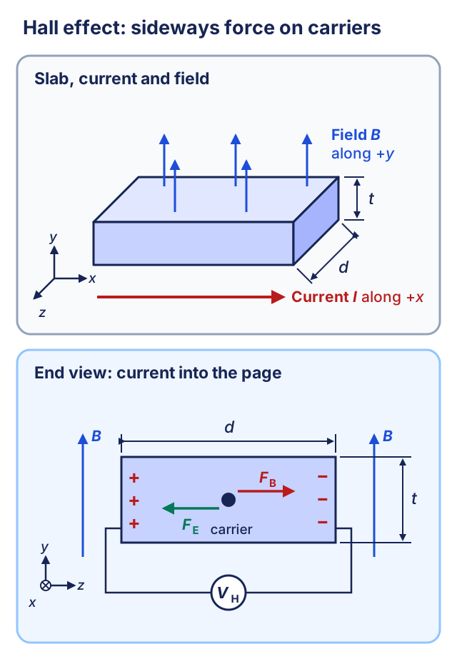
However, this build up of charge creates the Hall electric field that prevents the build-up of further charge. A steady state is reached where: F_B = F_E; Bqv_d = qE; Bv_d = V/d; B = V/v_dd; V = Bv_dd , where V is the hall voltage, vd is the drift velocity, d is the width of the conductor. Since I = Anv_dq, v_d = I/Anq Combining the equation for V and vd, V = Bd (I/Anq); V = BI/nq (d/A) Since the cross-sectional area A is equal to the product of the width of the sample d and its thickness t, (A = dt) V = BI/nqt The hall effect is used extensively to study conduction in materials, particularly in semiconductors. We have assumed so far that the mobile charge carriers within solids are electrons and this is in agreement with the sign of the Hall voltage for most materials. However, anomalous results can be obtained for metals such as aluminium or indium, and some semiconducting materials behave as if there were positive charge carriers in the materials. Back To Solid State Physics
Keep conventional current direction, magnetic-field direction, and chosen voltage polarity explicit. Most Hall-effect mistakes come from hidden sign flips, not formula errors.
Next steps
Continue with the next resource in this course.
Course and syllabus information
- Course
- Advanced Physics
- Edition
- Advanced Physics