Electric Circuits & Symbols
Key idea: Learn the standard O Level circuit symbols and how to draw neat circuit diagrams, including where to connect an ammeter, voltmeter, fuse and LED correctly.
Continue where you stopped
The core idea
On this page
Learning objectives
- Recognise and interpret circuit symbols for cells, batteries, switches, lamps, LEDs, resistors, fuses, ammeters and voltmeters
- Draw circuit diagrams with cells, batteries, switches, lamps, LEDs, fixed and variable resistors, fuses, ammeters and voltmeters
- Recognise and interpret circuit symbols for d.c. and a.c. supplies, potentiometers, bells, light-dependent resistors and thermistors
- Draw circuit diagrams with d.c. and a.c. supplies, potentiometers, bells, light-dependent resistors and thermistors
- Apply the same-current rule in series circuits
- Apply the potential-difference sum in series circuits
- Apply current conservation at parallel junctions
- Apply equal potential difference across parallel branches
- Calculate effective resistance in series
- Calculate effective resistance in parallel
- Solve whole-circuit problems using consistent quantities
- Describe variable-potential-divider action
- Describe NTC thermistor action as an input transducer
- Describe light-dependent resistor (LDR) action as an input transducer
- Solve simple NTC and LDR potential-divider problems
1. Definition
A. Electric circuit
An electric circuit is a set of components connected in a closed loop, so current can flow.
B. Circuit diagram
A circuit diagram is a drawing that uses standard symbols to show how circuit components are connected.
You should be able to draw circuit diagrams with: cell/battery, d.c. supply/a.c. supply, switch, lamp, resistor (fixed/variable), variable potential divider (potentiometer), fuse, ammeter, voltmeter, bell, LDR, thermistor and LED.
2. Key Ideas
- Use standard symbols (not pictures).
- Draw wires as straight lines with neat right-angle turns.
- Always draw a complete loop unless the question says the switch is open.
- Ammeter measures current → connect in series.
- Voltmeter measures p.d. → connect in parallel across the component.
- A fuse is connected in series to protect a circuit.
- A LED works only in one direction (needs correct polarity).
3. Detailed Explanations
A. The symbol sheet (what you must recognise)
Most exam questions expect you to use the standard symbols (especially meters and power sources).
B. Power sources: cell vs battery
- A cell is one source symbol.
- A battery is two or more cells in series.
A battery symbol repeats the unequal long–short line pair used for a cell. The longer line marks the positive terminal; a d.c. supply instead uses a circle labelled + and -.
C. Measuring current and p.d.
To measure current in a component, you must place the ammeter in series so the same current passes through it.
To measure p.d. across a component, you must place the voltmeter in parallel so it measures the voltage between the two ends.
Never connect an ammeter directly across a cell/power supply (it can act like a short circuit).
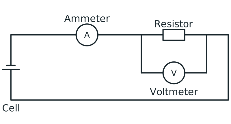
Voltmeter connection in parallel
Circuit with ammeter in series and voltmeter connected in parallel across a resistor to measure potential difference.
View figure data
| Part | Connection |
|---|---|
| Ammeter | In series in the main loop |
| Voltmeter | In parallel across the resistor |
| Resistor | In the conducting loop with the cell and ammeter |
D. Components you should recognise (quick notes)
- Variable resistor: used to change current (and in some circuits, to change output voltage as a potential divider).
- Potentiometer (variable potential divider): used to obtain a variable p.d. output (covered in Potential Divider).
- LDR: resistance decreases when light intensity increases (covered in LDR & Thermistor in Potential Dividers).
- NTC thermistor: resistance decreases when temperature increases (covered in LDR & Thermistor in Potential Dividers).
- LED: emits light when current flows through it in the correct direction.
4. Common Mistakes
- Drawing circuit “pictures” instead of symbols.
- Putting the ammeter in parallel or the voltmeter in series.
- Forgetting a closed loop (no current can flow).
- Forgetting LED direction/polarity.
5. Exam Tips
- Start by drawing the power source, then the main loop, then add branches.
- Keep symbols clear and label components (e.g. R₁, R₂) if needed.
- Write “ammeter in series” and “voltmeter in parallel” when explaining measurements.
6. Worked Examples
Modelled example 1
Series vs parallel (meters)
Problem
Study the worked solution
Place the ammeter
Method
Insert it in series with the lamp.Reason
The same charge-flow rate must pass through the meter and lamp.Working
Main loop: source → ammeter → lamp.Place the voltmeter
Method
Connect it in parallel across the two lamp terminals.Reason
Potential difference compares energy per charge between those two points.Working
Voltmeter branch spans the lamp only.
Guided practice 2
Drawing a basic measurement circuit
Problem
Build the main loop before the measurement branch
Hints
Hint 1: start with one closed path
Hint 2: add the voltage branch
View solution step by step
Draw the current path
Method
Join cell, switch, ammeter and lamp in one closed series loop.Reason
The ammeter must carry the lamp current.Working
Cell–switch–ammeter–lamp–cell.Add the p.d. measurement
Method
Draw a parallel voltmeter branch across the lamp.Reason
The branch endpoints must match the component endpoints.Working
Voltmeter connected only across lamp.
Common misconception 3
Symbols (recognition)
Learner response
Match labels and control marks
View solution step by step
Correct the meter labels
Method
Label A as ammeter and V as voltmeter.Reason
The letter identifies the quantity each circular meter reads.Working
A: current; V: potential difference.Correct the resistor label
Method
Label the resistor with an arrow as variable.Reason
The arrow represents an adjustable contact that changes resistance.Working
Resistor + arrow → variable resistor.
Examiner practice 4
Fuse placement
Examination question
Give placement, response and circuit effect
View solution step by step
Place the fuse
1 markMethod
Connect it in series with the protected circuit.Reason
All circuit current must pass through the fuse element.Working
Fuse lies in the main current path.Explain protection
2 marksMethod
State that excessive current heats and melts the fuse, opening the circuit.Reason
Breaking the path stops the damaging current.Working
Large I → fuse melts → current stops.
Self-mark with the mark scheme
Compare your response with each mark point. Select a point only when your response contains that evidence.
Self-mark placement, melting and circuit interruption.
Challenge 5
“What happens if you swap the meters?”
Fault-finding transfer
Use each ideal meter's resistance
Hints
Hint 1: voltmeter model
Hint 2: ammeter model
View solution step by step
Diagnose the series voltmeter
Method
State that its high resistance greatly reduces loop current, so the lamp may not light.Reason
A series element controls the same current through the whole path.Working
High series R → very small I.Diagnose the parallel ammeter
Method
State that its low resistance creates a near-short circuit and potentially very large current.Reason
Most current takes the low-resistance branch across the supply/component.Working
Low parallel R → dangerous large I.
7. Mind Stretchers
Mind stretcher 1: Why parallel for a voltmeter?Extension
Why is a voltmeter connected in parallel across a component instead of in series?
Show Answer
A voltmeter measures the potential difference between the two ends of the component. Connecting it in parallel puts it across the same two points, so it measures that p.d. directly.
Mind stretcher 2: Open switchExtension
A circuit diagram shows a switch drawn in the open position. What does that tell you about the current?
Show Answer
The circuit is not a closed loop, so no current flows.
8. Practice and next step
- Redraw the 16 required symbols from memory, then check polarity and the potentiometer’s third terminal against the reference figure.
- Complete the D.C. Circuits Quiz for circuit-diagram and meter-placement questions.
- Next, apply the symbols and meter connections in Series & Parallel Circuits.
Continue with the next resource in this course.
Course and syllabus information
- Course
- SEC G3 Physics
- Edition
- SEC G3 Physics 2027