A.C. Generator
Key idea: O Level electromagnetic induction: how a simple a.c. generator works, the role of slip rings, and the voltage–time graph.
Continue where you stopped
The core idea
On this page
Learning objectives
- State the properties of magnets
- Describe induced magnetism
- Distinguish temporary and permanent magnets
- Determine magnetic-field direction with a compass or bar magnet
- Interpret bar-magnet field patterns
- Draw the magnetic field pattern around a bar magnet and between the poles of two bar magnets
- Interpret the field pattern around a straight current-carrying wire
- Draw the magnetic field pattern around a straight current-carrying wire
- Interpret the field pattern around a current-carrying solenoid
- Draw the magnetic field pattern around a current-carrying solenoid
- Relate current magnitude and direction to magnetic field
- Describe electromagnet applications
- Describe experiments showing the force on a current-carrying conductor in a magnetic field
- Describe magnetic force on a charged-particle beam
- Predict force reversal when current or field reverses
- Use Fleming’s left-hand rule
- Explain the turning effect on a current-carrying coil
- Explain how current and turns increase the turning effect
- Describe split-ring commutator action
- Describe the effect of winding a motor coil on a soft-iron cylinder
- Deduce that a changing magnetic field can induce an e.m.f.
- Deduce that induced e.m.f. opposes the change producing it
- Deduce factors affecting induced e.m.f. magnitude
- Describe a simple a.c. generator and slip rings
- Sketch a simple a.c. generator voltage–time graph
- Describe a simple iron-cored transformer
- Apply ideal-transformer equations
- Explain cable loss and high-voltage transmission
1. Definition
An a.c. generator converts mechanical energy into electrical energy by electromagnetic induction.
You should be able to explain how an a.c. generator works, including the role of slip rings and why the induced e.m.f. changes direction.
2. Key Ideas
- Rotating coil in a magnetic field → changing magnetic flux → induced e.m.f.
- The induced e.m.f. reverses every half turn → alternating voltage.
- Slip rings keep the rotating coil connected to the external circuit while allowing a.c. output.
- Induced e.m.f. depends on how fast the coil cuts field lines:
- zero when motion is parallel to field lines
- maximum when cutting is most rapid
- To increase maximum e.m.f. (qualitative): stronger magnet, more turns, faster rotation, larger coil area.
3. Detailed Explanations
A. Main parts of a simple a.c. generator
- rotating coil in a magnetic field
- slip rings + carbon brushes (connection to external circuit)
The induction ideas and Lenz’s law are covered here: Electromagnetic Induction.
In the Motor, Generator & Transformer Lab, rotate the generator and connect the changing coil motion to the alternating output.
B. Why the output is alternating
As the coil turns, each side of the coil cuts the magnetic field in opposite directions on opposite halves of the rotation. So the induced e.m.f. changes direction every half turn.
C. Voltage–time graph (one full rotation)
The angle convention must be stated. In the graph below, 0° is the position where the plane of the coil is perpendicular to the magnetic field. Magnetic flux linkage is then greatest, but its rate of change is zero. With this convention:
- at 0° and 180°, induced e.m.f. is zero
- at 90°, induced e.m.f. is maximum in one direction
- at 270°, induced e.m.f. is maximum in the opposite direction
A.C. generator output: induced e.m.f. over one rotation
Schematic sine-wave output of a rotating-coil a.c. generator: the induced e.m.f. reverses every half turn.
Scroll across the graph to read all labels.
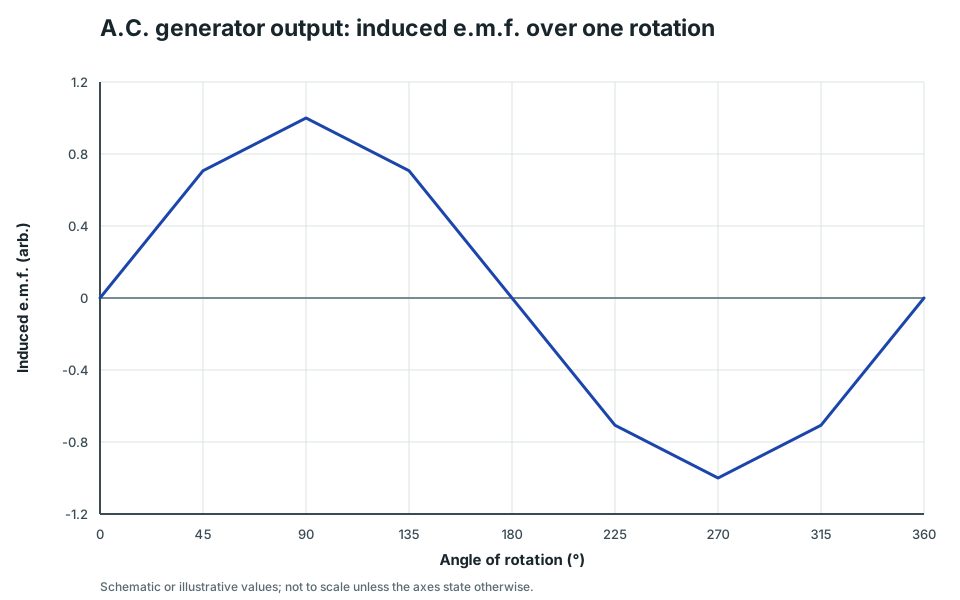
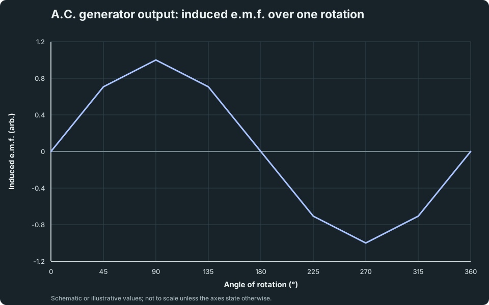
View figure data
| Angle of rotation (°) | e.m.f. |
|---|---|
| 0 | 0 |
| 45 | 0.707 |
| 90 | 1 |
| 135 | 0.707 |
| 180 | 0 |
| 225 | -0.707 |
| 270 | -1 |
| 315 | -0.707 |
| 360 | 0 |
D. Slip rings vs split-ring commutator
- Slip rings: a.c. generator (output remains a.c.)
- Split-ring commutator: d.c. motor (reverses current every half turn so torque stays one direction)
Split-ring commutator is covered in: DC Motor.
E. Practical design note (turning magnets)
Large generators often rotate a magnet or electromagnet (the rotor) inside stationary coils (the stator). The relative motion still changes the magnetic flux through the coils and induces an alternating e.m.f. Keeping the output coils stationary also lets their terminals connect directly to the external circuit; this construction detail does not change the induction principle shown above.
4. Common Mistakes
- Mixing up slip rings (generator) with split-ring commutator (motor).
- Saying current flows without a complete external circuit (need a closed circuit for current).
- Saying the coil “creates energy” (mechanical energy is converted to electrical energy).
- Memorising the 0°, 90° pattern without checking how the question defines the coil’s starting angle.
5. Exam Tips
- Use the phrase: “changing magnetic flux → induced e.m.f.”
- In graph questions, state your angle convention before assigning zero and maximum e.m.f. positions.
- For “increase output”: list turns, field strength, speed, area.
6. Worked Examples
Modelled example 1
When is e.m.f. zero?
Problem
Study the worked solution
Use the motion condition
Method
Identify instants when active coil sides move parallel to field lines.Reason
They do not cut magnetic field lines at that instant, so flux linkage has zero instantaneous rate of change.Working
Parallel motion → induced e.m.f. = 0.Map to the stated angles
Method
Give 0°, 180° and again 360° for a complete cycle.Reason
The page defines 0° with the coil plane perpendicular to the field.Working
E(0°) = E(180°) = E(360°) = 0
Guided practice 2
Increasing maximum e.m.f.
Problem
Choose two independent design variables
Hints
Hint 1: rate
Hint 2: linkage
View solution step by step
Increase the change rate
Method
Rotate the coil faster.Reason
Flux linkage changes more rapidly.Working
Rotation speed ↑ → |E|ₘₐₓ↑.Increase linked flux
Method
Use a stronger field, more turns or a larger coil area.Reason
Each makes the flux-linkage change larger during the rotation.Working
B↑, N↑ or area ↑ → |E|ₘₐₓ↑.
Common misconception 3
Slip rings purpose
Learner response
Separate contact function from induction reversal
View solution step by step
State the contact function
Method
Say slip rings maintain electrical contact between the rotating coil and stationary brushes.Reason
Each coil end remains connected to its own continuous ring.Working
Slip rings: continuous contact without connection swapping.Locate the output reversal
Method
State that the induced e.m.f. reverses because coil-side motion through the field reverses every half turn.Reason
Electromagnetic induction, not ring switching, produces the alternating sign.Working
Half-turn motion reversal → induced e.m.f. reversal.
Examiner practice 4
Output direction change
Examination question
Track the same coil side after 180°
View solution step by step
Reverse conductor motion
2 marksMethod
State that after half a turn each active side moves through the field in the opposite direction.Reason
Its velocity relative to the field has reversed.Working
180° rotation → cutting direction reverses.Reverse the electrical output
1 markMethod
State that induced e.m.f. reverses and current reverses if the circuit is closed.Reason
The generator-rule direction changes with conductor motion.Working
E reverses; closed circuit → I reverses.
Self-mark with the mark scheme
Compare your response with each mark point. Select a point only when your response contains that evidence.
Self-mark motion, induced e.m.f. and closed-circuit current.
Challenge 5
Faster rotation
Waveform transfer
Track cycle time and flux-change rate separately
Hints
Hint 1: frequency
Hint 2: amplitude
View solution step by step
Increase frequency
Method
State that cycles become closer together and frequency rises.Reason
More rotations and hence more cycles occur per second.Working
Rotation rate ↑ → f↑.Increase peak magnitude
Method
State that the graph has taller positive and negative peaks.Reason
The maximum rate of flux-linkage change is greater.Working
Rotation rate ↑ → |E|ₘₐₓ↑.
7. Mind Stretchers
Mind stretcher 1: Why a.c. is useful for transformersExtension
Why is it useful that the output of a generator is a.c. for transformers?
Show Answer
A transformer needs a changing current to produce a changing magnetic field, which induces a voltage in the secondary coil. a.c. provides a continually changing current.
Mind stretcher 2: Making d.c. from the generatorExtension
What change would you make to the connections if you wanted the output to be d.c. instead of a.c.?
Show Answer
Replace the slip rings with a split-ring commutator, which reverses the coil connections every half turn so the external output is in one direction.
8. Practice and next step
Change rotation speed in the Motor–Generator–Transformer Lab and connect frequency with peak e.m.f., then continue to Transformers.
Continue with the next resource in this course.
Course and syllabus information
- Course
- SEC G3 Physics
- Edition
- SEC G3 Physics 2027