Principles Of Electromagnetic Induction & Lenz's Law
Key idea: O Level electromagnetic induction: changing magnetic flux induces an e.m.f., Lenz’s law for direction, and factors affecting induced e.m.f.
Continue where you stopped
The core idea
On this page
Learning objectives
- State the properties of magnets
- Describe induced magnetism
- Distinguish temporary and permanent magnets
- Determine magnetic-field direction with a compass or bar magnet
- Interpret bar-magnet field patterns
- Draw the magnetic field pattern around a bar magnet and between the poles of two bar magnets
- Interpret the field pattern around a straight current-carrying wire
- Draw the magnetic field pattern around a straight current-carrying wire
- Interpret the field pattern around a current-carrying solenoid
- Draw the magnetic field pattern around a current-carrying solenoid
- Relate current magnitude and direction to magnetic field
- Describe electromagnet applications
- Describe experiments showing the force on a current-carrying conductor in a magnetic field
- Describe magnetic force on a charged-particle beam
- Predict force reversal when current or field reverses
- Use Fleming’s left-hand rule
- Explain the turning effect on a current-carrying coil
- Explain how current and turns increase the turning effect
- Describe split-ring commutator action
- Describe the effect of winding a motor coil on a soft-iron cylinder
- Deduce that a changing magnetic field can induce an e.m.f.
- Deduce that induced e.m.f. opposes the change producing it
- Deduce factors affecting induced e.m.f. magnitude
- Describe a simple a.c. generator and slip rings
- Sketch a simple a.c. generator voltage–time graph
- Describe a simple iron-cored transformer
- Apply ideal-transformer equations
- Explain cable loss and high-voltage transmission
1. Definition
Electromagnetic induction is the production of an e.m.f. in a conductor when the magnetic field (magnetic flux) linking it changes.
You should be able to describe electromagnetic induction and use Lenz’s law to show that the induced effect opposes the change producing it.
Change the motion, field strength, and number of turns in the Magnetism & Induction Lab, then explain each result using the rate of change of magnetic flux linkage.
2. Key Ideas
- A changing magnetic field/flux induces an e.m.f..
- Induced current flows only if the circuit is closed.
- Lenz’s law: in a closed circuit, the induced current produces an effect that opposes the change causing it.
- A faster change in flux → a larger induced e.m.f.
- Factors that increase induced e.m.f. (qualitative):
- move magnet/coil faster
- use a stronger magnet
- increase number of turns in the coil
- increase coil area
3. Detailed Explanations
A. When is an e.m.f. induced?
An e.m.f. is induced whenever the magnetic field linking a conductor/coil is changing, for example:
- moving a magnet into/out of a coil
- moving a coil in a magnetic field
- changing the current in a nearby coil (changing magnetic field)
Investigation: magnet and coil
- Connect a coil to a sensitive centre-zero galvanometer. Check that it reads zero when nothing moves.
- Push one pole of a bar magnet into the coil and record the direction and size of the deflection.
- Hold the magnet still inside the coil. The reading returns to zero because the flux linkage is no longer changing.
- Pull the same pole out. The deflection reverses because the change in flux linkage has reversed.
- Repeat by moving the magnet faster, using a stronger magnet or increasing the coil turns. Change only one factor at a time and compare peak deflections.
The experiment separates three ideas clearly: motion that changes flux linkage produces an e.m.f.; reversing the change reverses its direction; increasing the rate of change increases its magnitude. If the circuit is open, use a voltmeter to observe the induced e.m.f.—do not claim a continuous current.
A strong magnet is held still inside a 500-turn coil. Explain why the galvanometer reads zero, then name two different changes that would produce a larger momentary deflection.
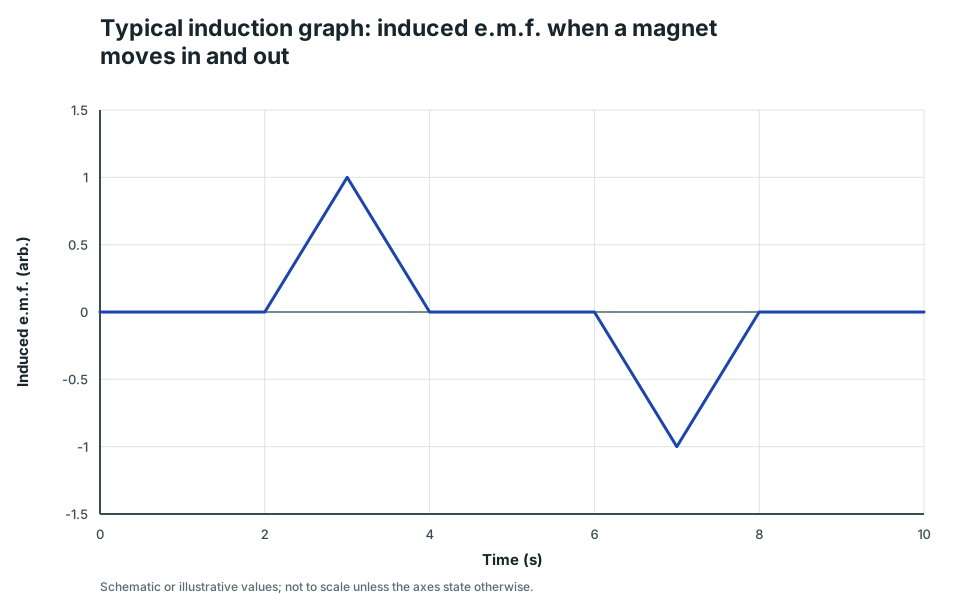
Typical induction graph: induced e.m.f. when a magnet moves in and out
A schematic induced e.m.f. vs time graph: one pulse when the magnet enters the coil and an opposite pulse when it leaves.
Scroll across the graph to read all labels.
View figure data
| Time (s) | e.m.f. |
|---|---|
| 0 | 0 |
| 2 | 0 |
| 3 | 1 |
| 4 | 0 |
| 6 | 0 |
| 7 | -1 |
| 8 | 0 |
| 10 | 0 |
B. Lenz’s law (direction)
Lenz’s law says the induced current produces a magnetic effect that opposes the change that produced it. It does not oppose the magnetic field itself.
Example with a coil and a magnet:
- If a north pole approaches the coil, the coil produces a north pole on the near side to repel it (opposes approach).
- If a north pole moves away, the coil produces a south pole on the near side to attract it (opposes separation).
C. Lenz’s law and Fleming’s right-hand rule
Use Fleming’s right-hand rule when a conductor moves in a magnetic field (generator rule):
- first finger: magnetic field (N → S)
- thumb: motion of the conductor
- second finger: induced current
4. Common Mistakes
- Saying a constant magnetic field induces an e.m.f. (you need a changing field/flux).
- Forgetting: induced current only flows in a closed circuit.
- Using “induced e.m.f.” and “induced current” as if they mean the same thing. A changing flux can induce an e.m.f. in an open circuit, but continuous current needs a closed path.
- Writing “the induced current helps the change” (it opposes the change).
5. Exam Tips
- Look for the trigger: “moving magnet/coil” or “changing magnetic field”.
- For direction, write “opposes the change” (Lenz’s law) and explain with attract/repel.
- For magnitude: “bigger/faster change → bigger induced e.m.f.” (faster motion, stronger magnet, more turns, larger area).
- If the question gives an open circuit or voltmeter, discuss e.m.f. first; only claim a current when there is a complete conducting path.
6. Worked Examples
Modelled example 1
Lenz’s law (approaching magnet)
Problem
Study the worked solution
Identify the change
Method
State that north-pole flux through the coil is increasing as the magnet approaches.Reason
Relative motion changes the magnetic flux linkage.Working
Approaching N → increasing linkage.Oppose the approach
Method
Make the near coil face north.Reason
A north face repels the approaching north pole and opposes the change causing induction.Working
Induced near face N → N–N repulsion.
Guided practice 2
Closed circuit vs open circuit
Problem
Answer the two quantities independently
Hints
Hint 1: emf trigger
Hint 2: current condition
View solution step by step
Induced e.m.f.
Method
State that an e.m.f. is induced.Reason
Moving the magnet changes flux linkage through the coil.Working
Changing flux linkage → induced e.m.f.Induced current
Method
State that no continuous current flows.Reason
The open circuit has no complete path.Working
Open path → I = 0 despite induced e.m.f.
Common misconception 3
Increasing induced e.m.f.
Learner response
Increase flux-linkage change or its rate
View solution step by step
Increase the rate of change
Method
Move the magnet or coil faster.Reason
The same flux change occurs in less time, increasing the induced e.m.f.Working
Motion speed ↑ → rate of flux-linkage change ↑.Increase linkage per change
Method
Increase coil turns or coil area.Reason
More turns link the changing field, or a larger area intercepts more changing flux.Working
N↑ or area ↑ → induced e.m.f. magnitude ↑.
Examiner practice 4
Magnet moving away
Examination question
Oppose separation rather than approach
View solution step by step
Reverse the current
1 markMethod
State that induced current reverses relative to the approach case.Reason
The direction of flux-linkage change has reversed.Working
Approach ↔ withdrawal → induced-current reversal.Choose the near pole
2 marksMethod
Make the coil’s near face south.Reason
It attracts the receding north pole and opposes their increasing separation.Working
Receding N beside induced S → attraction.
Self-mark with the mark scheme
Compare your response with each mark point. Select a point only when your response contains that evidence.
Self-mark current reversal, near pole and Lenz-law reason.
Challenge 5
Faster motion
Graph-feature transfer
Hold total flux change fixed and change its time
Hints
Hint 1: pulse height
Hint 2: pulse width
View solution step by step
Predict the magnitude
Method
State that the pulse has a larger peak magnitude.Reason
The rate of change of flux linkage is greater.Working
Faster motion → |E|ₚₑₐₖ↑.Predict the duration
Method
State that the pulse is narrower in time.Reason
The same start-to-end movement occurs more quickly.Working
Motion time ↓ → pulse duration ↓.
7. Mind Stretchers
Mind stretcher 1: Energy sourceExtension
Why must you do work (use energy) to push a magnet into a coil that is connected to a complete circuit?
Show Answer
The induced current produces a magnetic effect that opposes the magnet’s motion (Lenz’s law). You must do work against this opposing effect. The mechanical energy you supply is converted into electrical energy in the circuit.
Mind stretcher 2: Open vs closed circuitExtension
Why can an induced e.m.f. exist even when there is no induced current (open circuit)?
Show Answer
An e.m.f. can be induced by a changing magnetic flux, but current requires a complete conducting path. With an open circuit there is no closed path, so charges cannot flow continuously even though a potential difference is produced.
8. Practice and next step
Predict the sign and size of each induced-e.m.f. pulse in the Magnetism & Induction Lab. Then use the Electromagnetic Induction check before continuing to the A.C. Generator.
Continue with the next resource in this course.
Course and syllabus information
- Course
- SEC G3 Physics
- Edition
- SEC G3 Physics 2027