Resistor In An A.C. Circuit
Consider a resistor with resistance R through which there is a sinusoidal current:
$$i = I \cos{\omega t}$$
From Ohm’s Law,
$$\begin{aligned} v_{R} &= iR \\ &= \left( IR \right) \cos{\omega t} \\ &= V_{R} \cos{\omega t} \end{aligned}$$
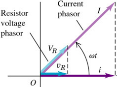
The current $i$ is in phase with the voltage $v_{R}$
The instantaneous power $p$ delivered to a resistor with resistance R:
$$\begin{aligned} p &= iV \\ &= IV \cos^{2}{\omega t} \\ &= \frac{1}{2} IV \left( 1 + \cos{2 \omega t} \right) \end{aligned}$$
The average power is given by:
$$\begin{aligned} P_{\text{av}} &= \frac{1}{2} IV \\ &= \frac{I}{\sqrt{2}} \frac{V}{\sqrt{2}} \\ &= I_{\text{rms}}V_{\text{rms}} \end{aligned}$$
The average power can also be expressed as:
$$\begin{aligned} P_{\text{av}} &= I_{\text{rms}}^{2}R \\ &= \frac{V_{\text{rms}}^{2}}{R} \end{aligned}$$
Inductor In An A.C. Circuit
Consider a pure inductor with self-inductance L and zero resistance, through which there is a sinusoidal current:
$$i = I \cos{\omega t}$$
We know that:
$$\begin{aligned} v_{L} &= L \frac{di}{dt} \\ &=-\left( I \omega L \right) \sin{\omega t} \\ &= V_{L} \cos{\left( \omega t + 90^{\circ} \right)} \end{aligned}$$
From the equation above, we can see that the current and voltage are “out of step” or out of phase by a quarter-cycle.
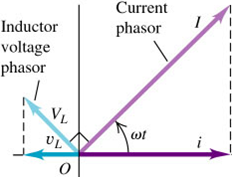
Since the voltage peaks occur a quarter-cycle earlier than the current peaks, we say that the voltage leads the current by $90^{\circ}$.
The inductive reactance of an inductor:
$$\begin{aligned} X_{L} &= \omega L \\ V_{L} &= IX_{L} \end{aligned}$$
The instantaneous power $p$ delivered to a pure inductor L:
$$\begin{aligned} p &= iv \\ &=-IV \cos{\omega t} \sin{\omega t} \\ &=-\frac{1}{2} IV \sin{2 \omega t} \end{aligned}$$
The average power:
$$P_{\text{av}} = 0$$
The net energy transfer over one cycle is zero.
Example: An Inductor In An A.C. Circuit
Suppose you want the current amplitude in a pure inductor in a radio receiver to be $250 \, \mu \text{A}$ when the voltage amplitude is 3.60 V at a frequency of 1.60 MHz, the inductive reactance needed is:
$$\begin{aligned} V_{L} &= IX_{L} \\ X_{L} &= \frac{3.6}{250 \times 10^{-6}} \\ &= 14400 \Omega \end{aligned}$$
The inductance needed is:
$$\begin{aligned} X_{L} &= \omega L \\ L &= \frac{X_{L}}{2 \pi f} \\ &\approx 0.00143 \, \text{H} \end{aligned}$$
Capacitor In An A.C. Circuit
Consider a capacitor with capacitance C through which there is a sinusoidal current:
$$i = I \cos{\omega t}$$
The charge stored in the capacitor will be given by:
$$q = \frac{I}{\omega} \sin{\omega t}$$
We know that:
$$\begin{aligned} v_{C} &= \frac{q}{C} \\ &= \left( \frac{I}{\omega C} \right) \sin{\omega t} \\ &= V_{C} \cos{\left( \omega t-90^{\circ} \right)} \end{aligned}$$
The current and voltage are “out of step” or out of phase by a quarter-cycle.

Since the voltage peaks occur a quarter-cycle after the corresponding current peaks, we say that the voltage lags the current by $90^{\circ}$.
The capacitive reactance of a capacitor:
$$\begin{aligned} X_{C} &= \frac{1}{\omega C} \\ V_{C} &= IX_{C} \end{aligned}$$
The instantaneous power $p$ delivered to a pure capacitor C:
$$\begin{aligned} p &= iv \\ &= IV \cos{\omega t} \sin{\omega t} \\ &= \frac{1}{2} IV \sin{2 \omega t} \end{aligned}$$
The average power is:
$$P_{av} = 0$$
The net energy transfer over one cycle is zero.
Example: A Capacitor & A Resistor In An A.C. Circuit
A $200 \, \Omega$ resistor is connected in series with a $5.00 \, \mu F$ capacitor. The voltage across the resistor is $v_{R} = \left( 1.20 \, \text{V} \right) \cos{\left[ \left( 2500 \, \text{rad s}^{-1} \right)t \right]}$. Find the circuit current, capacitive reactance of capacitor and voltage across capacitor.
Circuit current:
$$\begin{aligned} i &= \frac{v_{R}}{R} \\ &= \left( 6.00 \, \text{mA} \right) \cos{\left[ \left( 2500 \, \text{rad s}^{-1} \right)t \right]} \end{aligned}$$
Capacitive reactance of capacitor:
$$\begin{aligned} X_{C} &= \frac{1}{\omega C} \\ &= \frac{1}{2500 \times 5 \times 10^{-6}} \\ &= 80.0 \, \Omega \end{aligned}$$
The voltage across the capacitor:
$$\begin{aligned} v_{C} &= IX_{C} \cos{\left[ \left( 2500 \, \text{rad s}^{-1} \right)t-\frac{\pi}{2} \right]} \\ &= \left( 0.480 \, \text{V} \right) \cos{\left[ \left( 2500 \, \text{rad s}^{-1} \right)t-\frac{\pi}{2} \right]} \end{aligned}$$
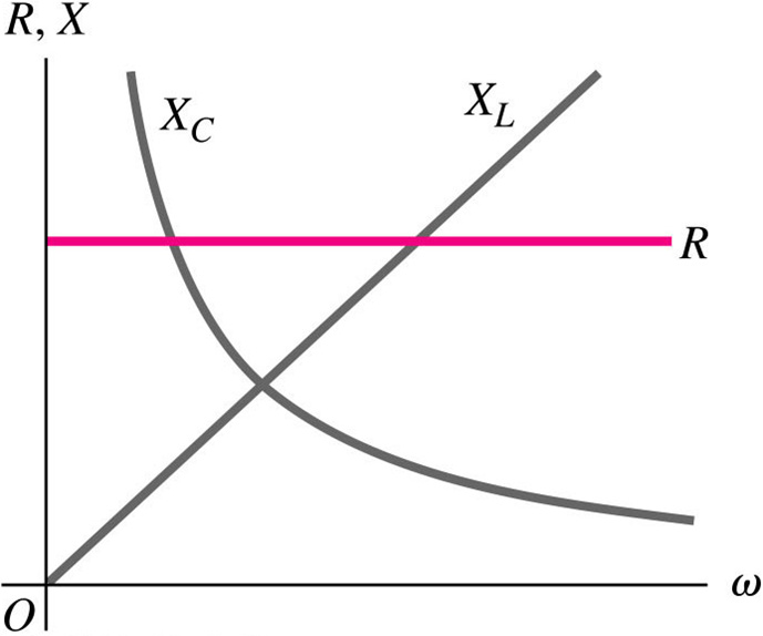
From the diagram above, we can see that the impedance of the inductor is low when the $\omega$ is small while the impedance of the capacitor is low when the $\omega$ is large. From this, we know that an inductor can function as a low-pass filter (blocks everything with a large $\omega$) while a capacitor can function as a high-pass filter (blocks everything with a small $\omega$).
Next: L-R-C Series Circuit With A.C.