Table of Contents
Ray Diagrams
Ray diagrams for plane mirrors are a straightforward way to visualize how images are formed by reflection. These diagrams help in understanding the path taken by light rays from an object to our eyes after reflecting off a mirror.
Step-By-Step Guide To Drawing Ray Diagrams For Plane Mirrors
Step 1: Draw the Mirror and the Object
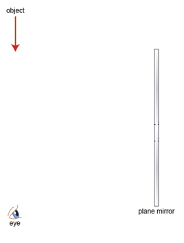
- Begin by drawing a straight line to represent the plane mirror. Label the line as the mirror.
- Choose a point or an object in front of the mirror. This is the object from which light rays will emanate. It’s common to represent the object as an arrow or a simple shape for clarity.
Step 2: Identify and Mark the Object Distance
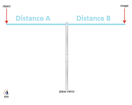
- Measure the distance from the object to the mirror. This distance is known as the object distance, often denoted by $d_{o}$, identified as “Distance A” in this diagram.
- “Distance B” is the image distance or the distance from the image to the mirror.
- Distance A is equal to Distance B and the image size is the same size as the object size.
- It’s crucial to maintain a consistent scale if you’re drawing a diagram for calculation purposes.
Step 3: Draw Reflected Rays To The Image
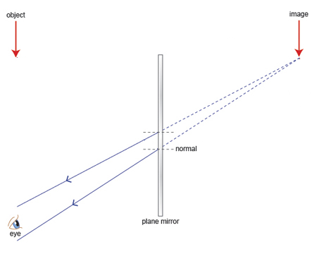
- From the top of the image, draw two or more rays towards the mirror and the eye. These are the reflected rays, the paths of light traveling from the mirror.
- Ray 1: Aim this ray towards the top of the eye
- Ray 2: Aim this ray towards the bottom of the eye
- These rays should be straight lines that strike the mirror at an incident point.
- Behind the mirror, the reflected rays should be extended and the extensions are dotted or dashed to indicate that they are not actual paths of light but rather the perceived paths. Broken lines from the image to mirror indicate virtual rays.
- The image is virtual – Virtual image: Light rays do not actually meet at the image position. Because of that, a virtual image cannot be projected on a screen.
Step 4: Use Law Of Reflection To Work Out Incident Rays
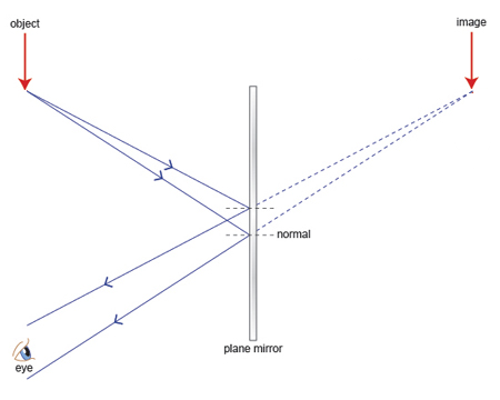
- At the point of incident, we recall that according to the Law Of Reflection, the angle of incidence is equal to the angle of reflection. We direct the reflected ray back to the object, which will form the incident ray.
- Check that the angles are correct – angle of incidence is equal to the angle of reflection
Properties Of Image Formed In Plane Mirror
- Same size as object
- Laterally inverted (Left becomes right, right becomes left)
- Upright
- Virtual
- As far behind the mirror as the object is in front
Worked Examples
Question 1: Understanding Image Formation
Consider a plane mirror and an object placed 5 units in front of it. If a ray of light emanates from the top of the object and reflects off the mirror to an observer’s eye, how would you draw the ray diagram to locate the image? Describe the steps and the properties of the image formed.
Click here to show/hide answer
- Draw the Mirror and the Object: Start by drawing a straight line to represent the plane mirror. Place an object, represented by an arrow, 5 units in front of the mirror.
- Mark the Object Distance: Measure and mark the distance from the object to the mirror as 5 units (Distance A).
- Draw Reflected Rays: From the top of the object, draw a ray towards the mirror. Upon hitting the mirror, reflect the ray towards the observer’s eye. Extend this reflected ray behind the mirror with a dotted line to represent the perceived path of the light.
- Use the Law of Reflection: Ensure the angle of incidence equals the angle of reflection where the ray strikes the mirror. This confirms the reflected ray’s path is correctly drawn.
- Properties of the Image: The image formed will be virtual (cannot be projected on a screen), upright, laterally inverted, and the same size as the object. It appears to be 5 units behind the mirror, mirroring the object’s distance.
Question 2: Critical Analysis of Ray Diagrams
Explain how the principle of laterally inverted images in plane mirrors is represented in ray diagrams. Use the concept of ray paths from an object to the observer’s eyes after reflection.
Click here to show/hide answer
In ray diagrams, lateral inversion is demonstrated by the way light rays reflect off the mirror to the observer. When an object’s light rays (e.g., from its left and right sides) reflect off a plane mirror, the rays follow the law of reflection. Due to the mirror’s reflective properties, the observer perceives the image’s left and right sides to be swapped compared to the object. This effect is depicted in the ray diagram by drawing reflected rays from the object to the observer’s eye, showing that the direction from which the light appears to come is reversed, hence illustrating lateral inversion. The reflected rays extend behind the mirror, creating a virtual image that is a mirror image of the object, thereby laterally inverted.
Question 3: Application of the Law of Reflection
A student draws a ray diagram with an angle of incidence of 30 degrees. However, the angle of reflection marked is 40 degrees. Critically evaluate this diagram in the context of the Law of Reflection. What corrections, if any, should be made?
Click here to show/hide answer
According to the Law of Reflection, the angle of incidence is equal to the angle of reflection. This means that if the angle of incidence is 30 degrees, the angle of reflection must also be 30 degrees. The student’s diagram inaccurately represents the Law of Reflection by marking the angle of reflection as 40 degrees. To correct this diagram, the angle of reflection should be adjusted to match the angle of incidence, ensuring both angles are 30 degrees. This correction ensures the diagram accurately reflects the behavior of light upon striking a plane mirror, adhering to the foundational principles of optics.
Question 4: Depth Perception in Ray Diagrams
How does a ray diagram for a plane mirror explain the perception of depth, i.e., the distance behind the mirror where the image appears to be located? Illustrate this concept with a ray diagram involving an object placed 10 units in front of a plane mirror.
Click here to show/hide answer
A ray diagram illustrates depth perception through the use of virtual rays extended behind the mirror. To explain this:
- Draw the Object and Mirror: Place the object 10 units in front of the straight line representing the mirror.
- Identify Object Distance: Mark the object’s distance to the mirror as 10 units (Distance A).
- Draw Reflected Rays: Draw rays from the object reflecting off the mirror towards the observer. Extend these rays behind the mirror as dotted lines.
- Perception of Depth: The dotted lines represent the path the light rays appear to travel from. By extending these reflected rays behind the mirror, the diagram shows that the observer perceives the image to be located 10 units behind the mirror, equal to the object’s actual distance in front. This method visually represents the concept of depth, as the virtual image appears to occupy space behind the mirror, giving the illusion of depth within a flat mirror.