Hall Effect
Show/Hide Lessons (Solid State Physics | H3 Physics)
- Types Of Bonds
- Potential Energy Diagram For Formation Of Bonds
- Potential Energy Diagram For The Formation Of a Van Der Waals' Bond
- Crystal Structure
- Close-packed Structures
- Hexagonal Close-packed Structure
- Drude Model Of Electrical Conduction
- Number Density Of Free Electrons
- Free Electron Theory Of Solids
- Current Density
- Resistance And Resistivity
- Temperature Dependence Of Resistivity
- Fermi-Dirac Statistics
- Fermi Level And Fermi Energy
- Fermi Function
- Energy Band Structures In Solids
- Electrical Conductivities Of Materials
- Zener Diode
- Hall Effect
- Electrical Characteristics Of Commercial Alloys
This page is kept indexable because Hall-effect interpretation is a durable H3 landing topic for carrier-sign and carrier-density reasoning.
Use this page for:
- deriving Hall voltage relations,
- identifying majority carrier sign from measured voltage direction,
- connecting microscopic drift variables to macroscopic measurements.
Fast start
- Magnetic force deflects moving carriers sideways.
- Charge separation builds an electric field until magnetic and electric forces balance.
- Hall voltage then encodes carrier sign and density information.
Imagine a conductor with rectangular cross-section d x t that is parallel to the y-z plane with (conventional) current passing in the positive x direction. With a magnetic field acting in the positive y direction, there is a Lorentz force on the charge carriers given by F = qvdB. Fleming’s left hand rule suggests that both positive and negative charge carriers should experience a force to the side of the conductor. 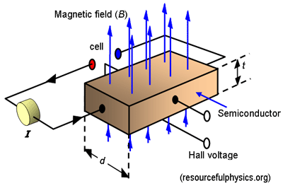 However, this build up of charge creates the Hall electric field that prevents the build-up of further charge. A steady state is reached where: FB = FE; Bqvd = qE; Bvd = V/d; B = V/vdd; V = Bvdd , where V is the hall voltage, vd is the drift velocity, d is the width of the conductor. Since I = Anvdq, vd = I/Anq Combining the equation for V and vd, V = Bd ( I/Anq ); V = BI/nq ( d/A ) Since the cross-sectional area A is equal to the product of the width of the sample d and its thickness t, (A = dt) V = BI/nqt The hall effect is used extensively to study conduction in materials, particularly in semiconductors. We have assumed so far that the mobile charge carriers within solids are electrons and this is in agreement with the sign of the Hall voltage for most materials. However, anomalous results can be obtained for metals such as aluminium or indium, and some semiconducting materials behave as if there were positive charge carriers in the materials. Back To Solid State Physics
Keep conventional current direction, magnetic-field direction, and chosen voltage polarity explicit. Most Hall-effect mistakes come from hidden sign flips, not formula errors.
Next steps
8. Practice, Quiz and Next Step
Close your notes and use Hall Effect in the supplied context below. This requires a constructed explanation or working, not recognition of an option.
Fresh context: An unfamiliar data set or physical system requires you to apply Hall Effect while stating the model, regime and assumptions.
- Retrieve: define hall effect in your own words, including units, sign or conditions where relevant.
- Represent: Choose and label an appropriate diagram, graph, table or symbolic model; derive or justify the relationship used.
- Apply: Reach a conclusion, then evaluate it using units, uncertainty, a limiting case and one practical or modelling limitation.
Check the response before looking back
- The model, regime, coordinates and assumptions are explicit.
- The derivation or multi-step reasoning is visible rather than implied.
- The conclusion is tested against units, data quality and a limiting case.
- A practical control, uncertainty or model limitation is evaluated where applicable.
If one check fails, name that exact gap, revisit the matching explanation or worked example, and redo the task with different values or a different situation. Then use theH3 Physics course hub orpractice browser for an independent re-test.
- H3
- Solid State Physics
- Lesson
- Physics